This is like a time machine, with the clock set back to 1975.
With a credit card and a soldering iron, you can start building a brand-new Altair 8800. Today!
About the only difference is that you can buy parts online with a credit card. You probably would have bought an original Altair kit by mailing a check to MITS, likely after seeing it advertised in a magazine.
I purchased my Altair 8800 case, front-panel and FDC+ disk controller from Mike Douglas at DeRamp.com. The Altair 8080 CPU board was from Gary Kaufman. And the 88-2SIOJP serial I/O card was from Martin Eberhard. Memory is included on the DeRamp FDC+ disk controller.
Links for each of these vendors is listed below:
Altair 8800 Reproduction Boards and Parts from Mike Douglas at DeRamp.com
Altair 8800 Reproduction Boards and Parts from Gary Kaufman at The-Planet.org
Altair 8800 Reproduction Boards and Parts from Jerry Walker at JMprecision.co.uk
S100 Computer Parts and Circuit Boards from Todd Goodman at S100computers.com
Most of the offerings are either complete assemblies or raw printed circuit boards with a bill-of-materials and schematic. They aren’t kits. But really, soldering chip sockets and passive parts on a printed circuit board isn’t hard. Especially when the boards have a solder-mask and clearly marked silkscreen.
I started my build with the front-panel. I soldered the resistors, capacitors and chip sockets onto the front panel board. Then I used the front panel mounting bracket as a jig, to help align and mount the switches.
Using four spray can lids as supports for the bracket, I set in place all the switches. Finger-tightened the nuts to hold each switch in place, and set the circuit board upon the switches, making sure all three lugs for each switch protrude though their plate-through holes on the printed circuit board. Once that was accomplished, I soldered 'em all in place.
The switches all have a slot in the threads. The front-panel is made more attractive when all the switches are oriented so that the slot is downwards.
Once I soldered all the switches in place, I flipped over the mounting plate to see the switches.

Front-panel assembly |

Switches on mounting plate |
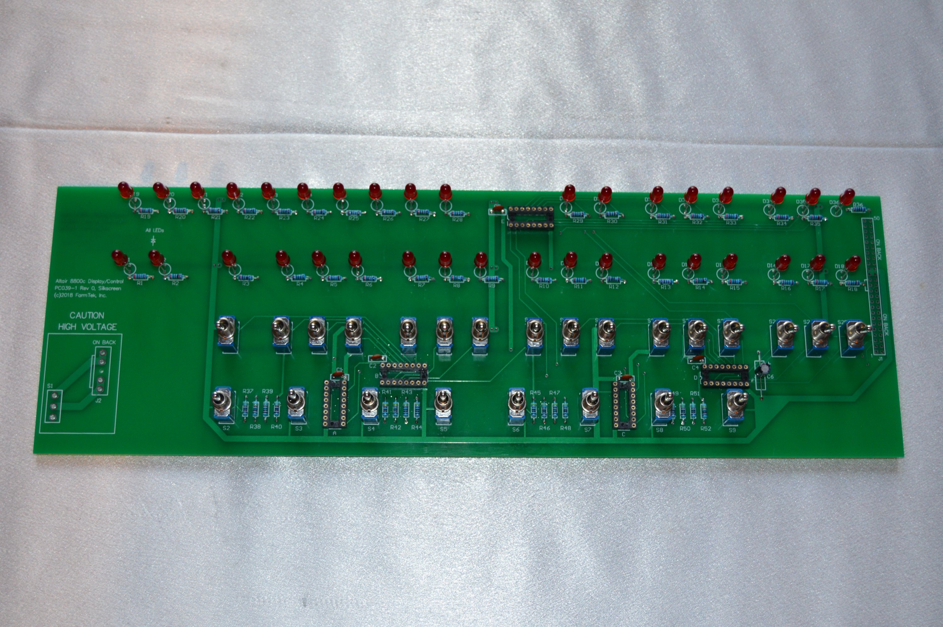
Next step was to solder on the front-panel lights.
I removed the front-panel PCB from the mounting panel, and inserted all the LEDs. Then pushed the front-panel board onto the front face. Placed the 5/8" spacers between the PCB and front face to set spacing. Soldered one lead on each LED. That way if any needed adjustments, it could be easily done. As I was satisfied with the alignment of each LED, I would solder its second lead for final placement. Essentially, I used the front-face as a jig to place and align the LEDs.

Front-panel board without LEDs |

Installing the lights |
After all the parts were soldered in place, I cleaned the board really well with flux remover.
Then I "finger tightened" a few of the nuts as a final test-fit of the front-panel board on the chassis mount including the front face.
Front-panel board with lights installed |
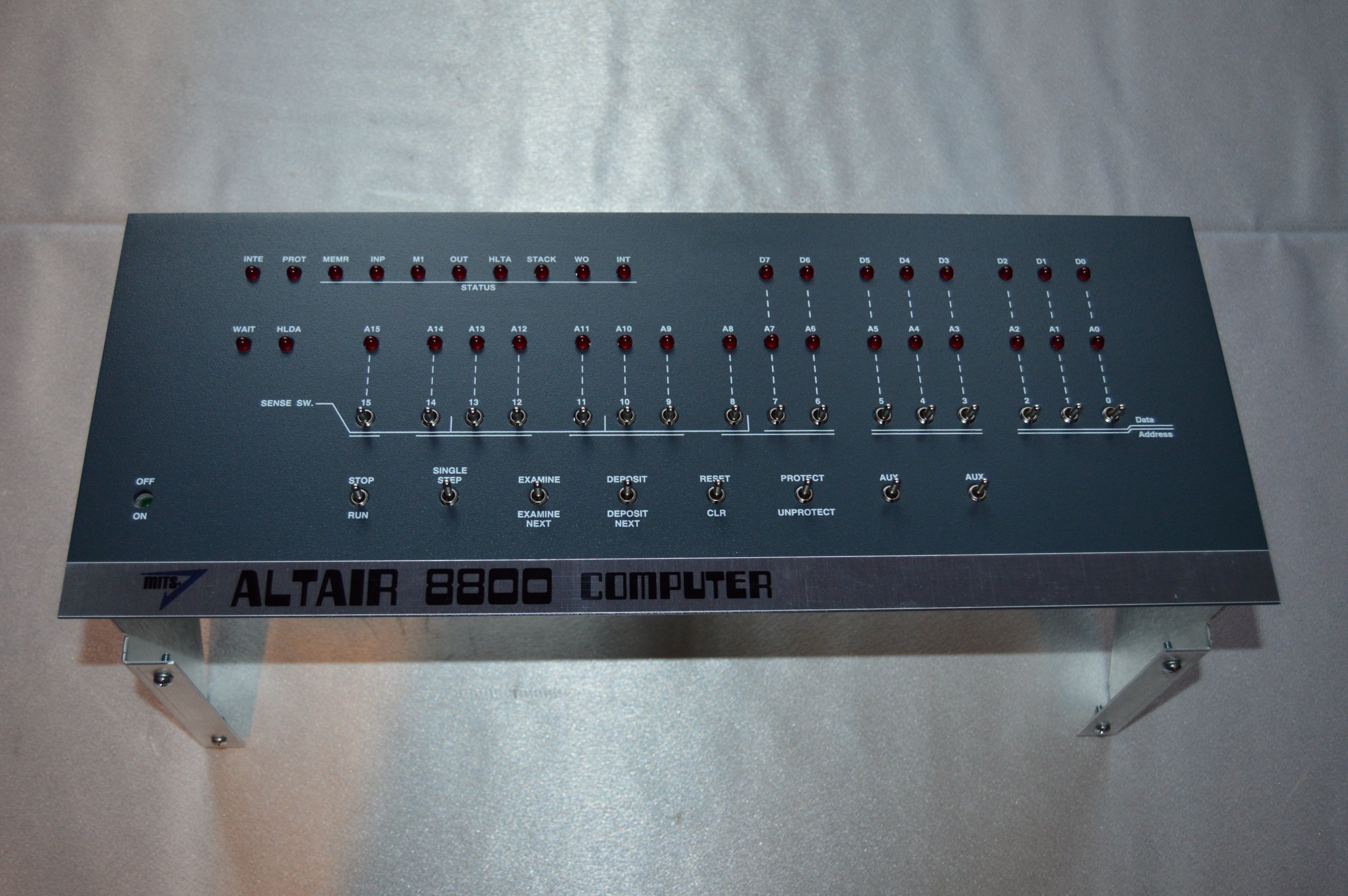
Test fit of the completed front-panel on the chassis mount |
Next step - Building the front-panel interface and CPU boards.
The front-panel interface PCB was simple to build, just a handful of socketed chips, a voltage regulator and heat-sink and a couple connectors.
The processor board has many more passive components, but was not difficult to build either.
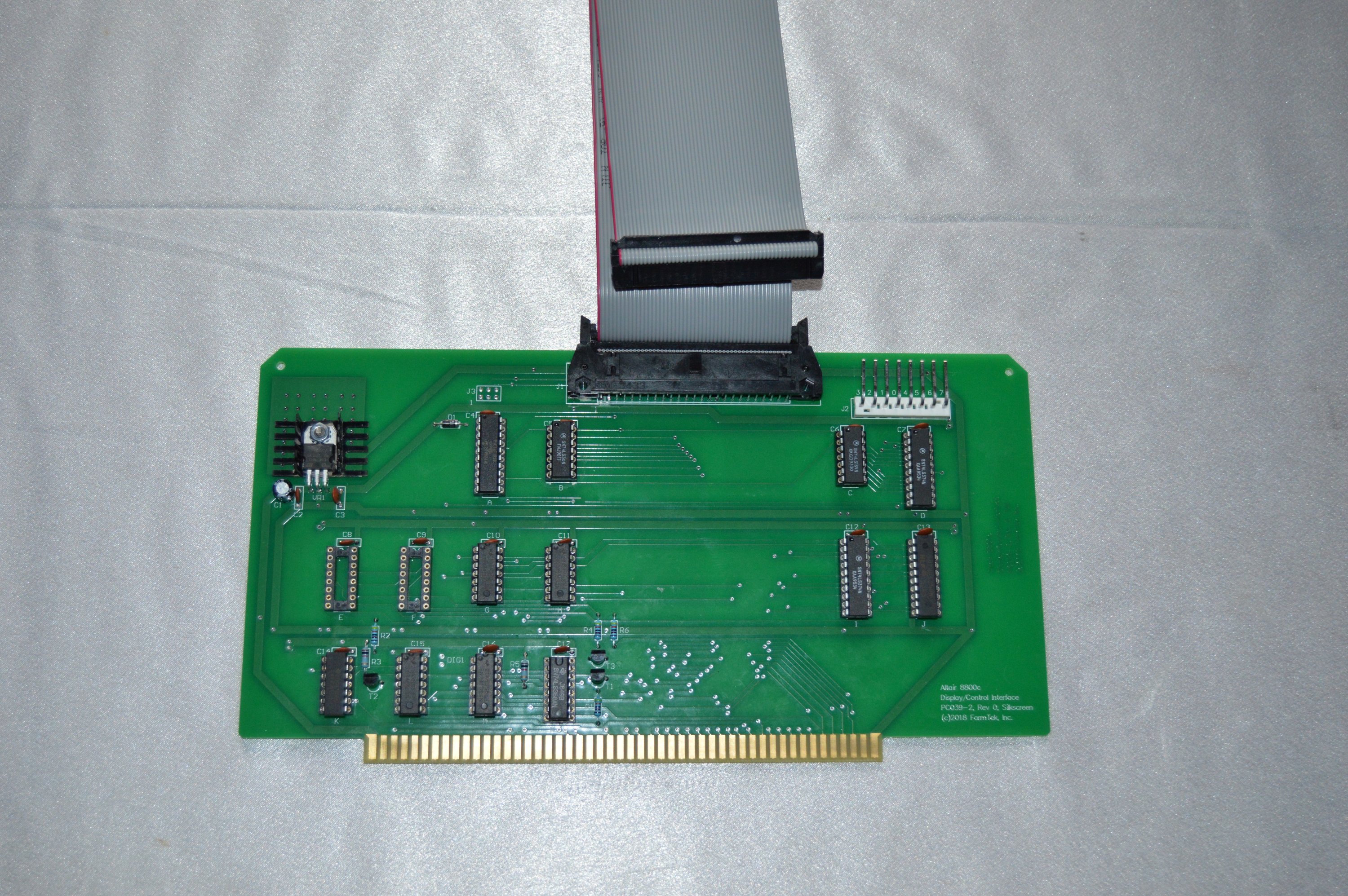
Front-panel interface board |
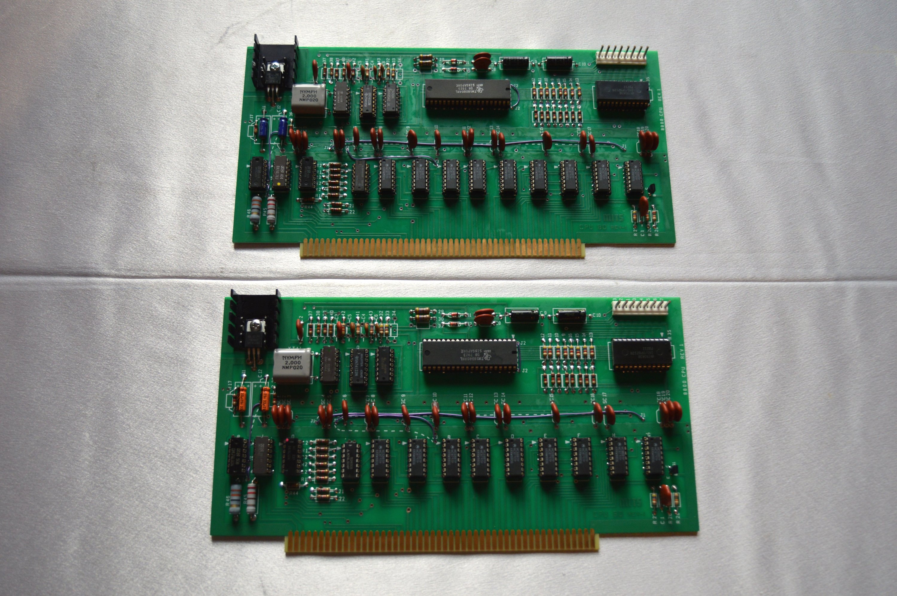
8080 CPU boards for Altair 8800c |
I bought a couple Altair 8800 CPU boards from Gary Kaufman and parts kits from tpKirkp. Only one is needed, of course, but I think it's good to have spare boards because it makes troubleshooting so much easier as time goes by. So I decided to build two whole systems. If something breaks, I can swap boards to find the defective board, and then swap chips to find the defective chip. Just makes maintenance easier.
I purchased Mike Douglas' FDC+ disk controller board and Martin Eberhard's 88-2SIOJP serial board. And I have a handful of old Teac floppy drives so the only thing that remained was the backpanel and power supplies. To provide the juice, I purchased a MeanWell HRP-75-7.5 (7.5v 10 amp) supply and two MeanWell RS-15-15 (15v 1A) supplies. These provide +8v and +/-16v to the system.
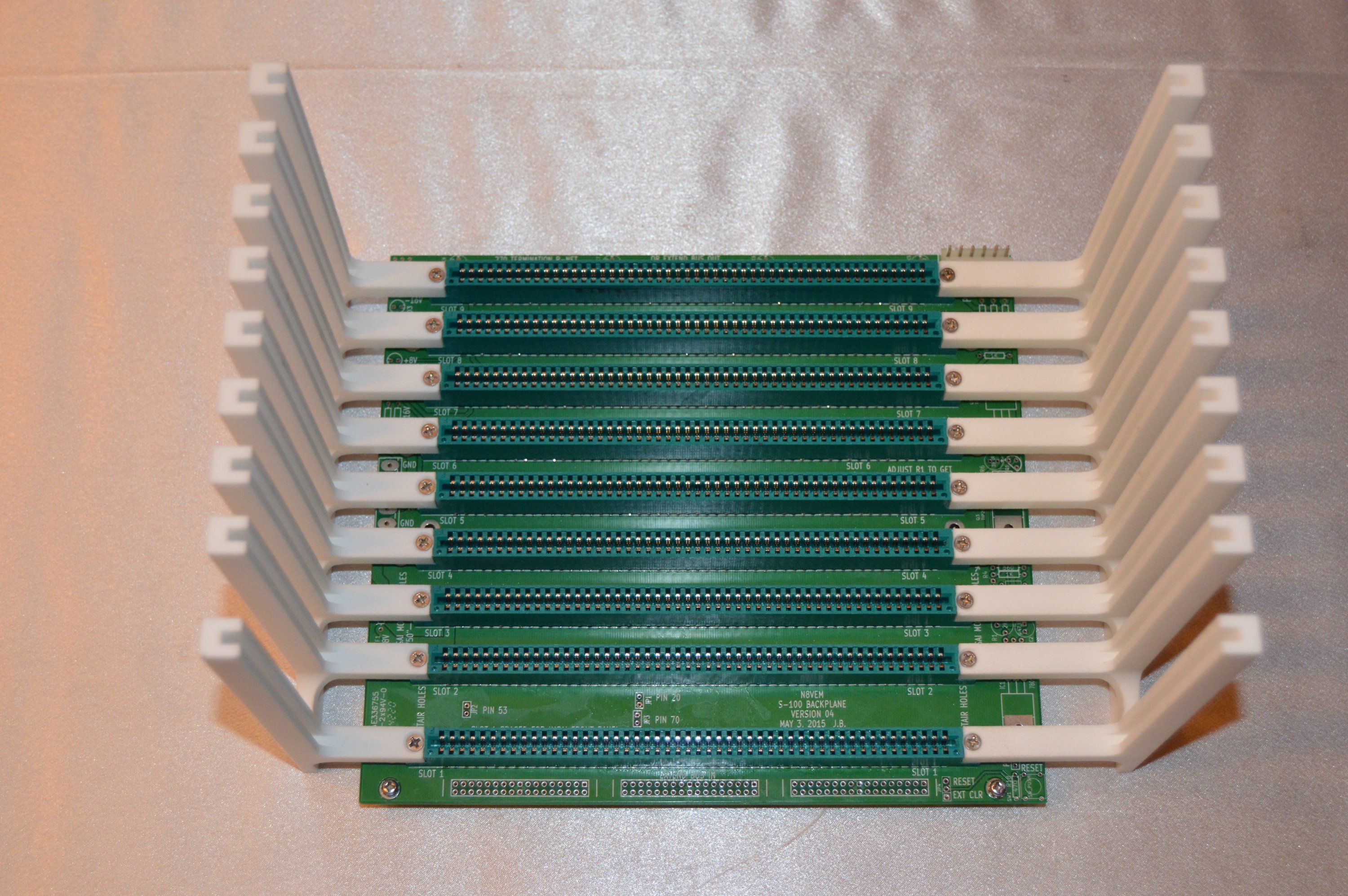
I got the 9-slot backpanel and edge connectors from Todd Goodman at S100computers.com. I also got a few unpopulated S-100 boards from him, but they're projects for a later date.
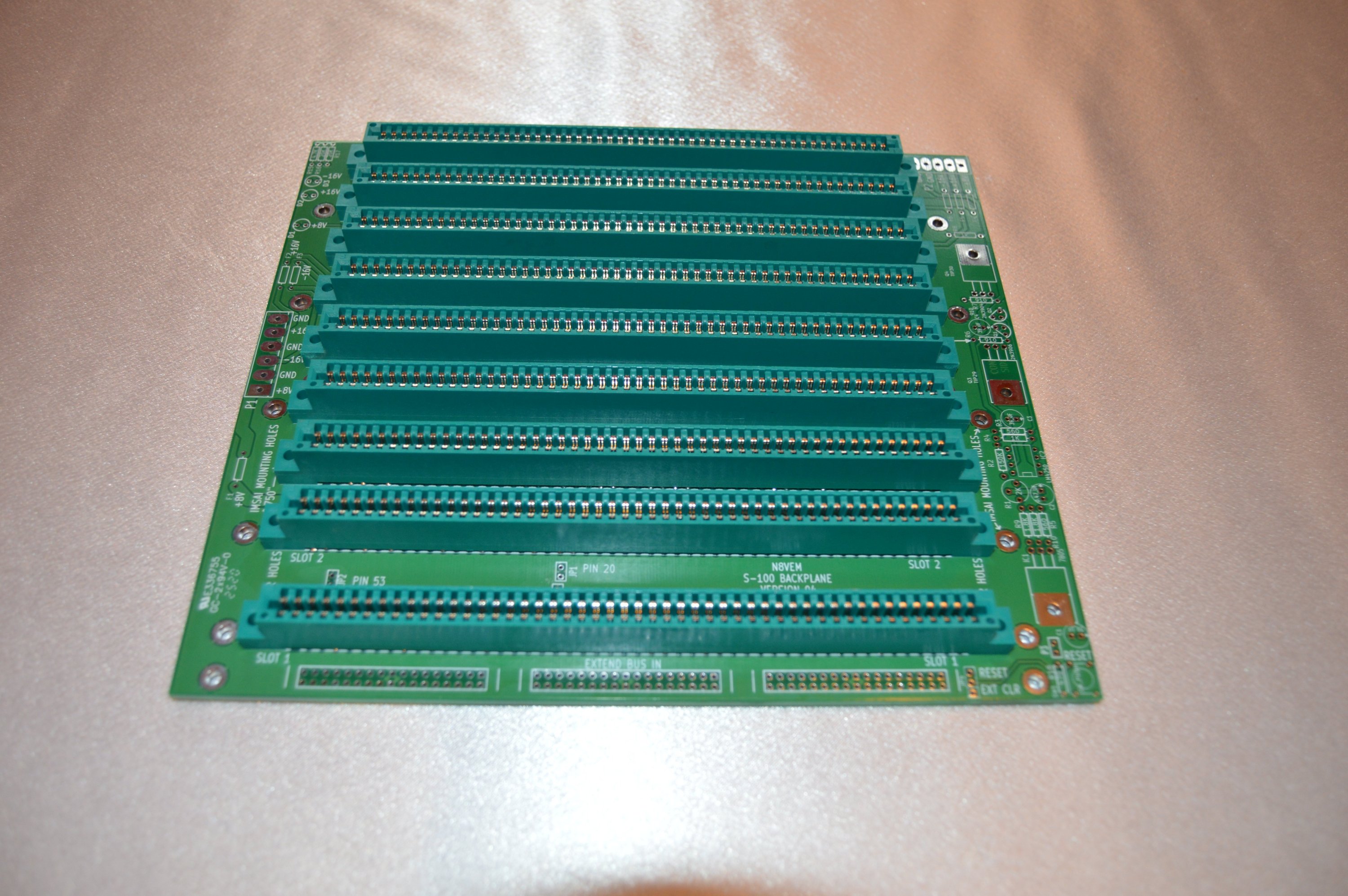
Backplane board with nine edge connectors installed |
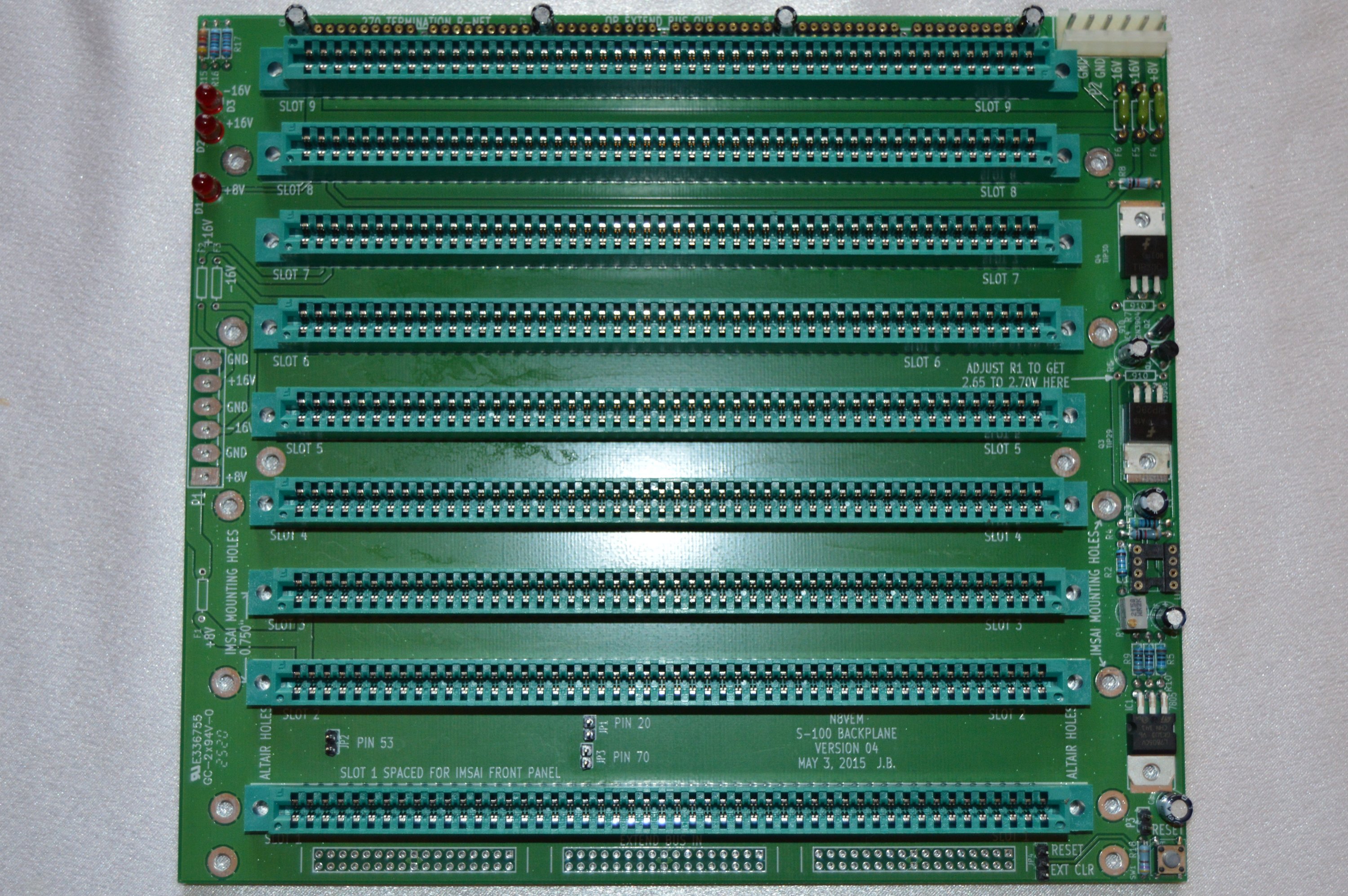
9-slot backplane, fully populated |
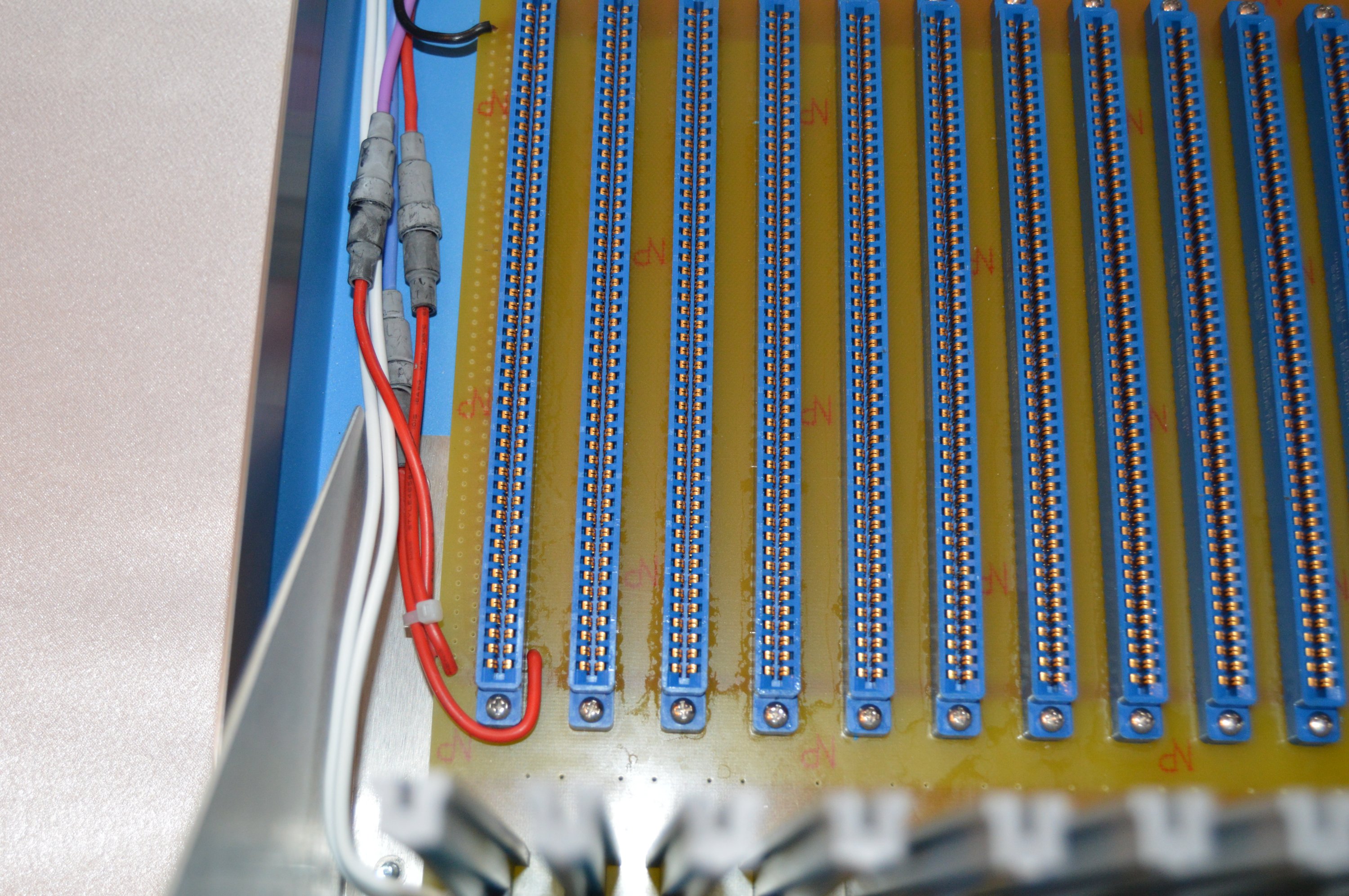
If you click on the "fully populated" 9-slot backplane photo above and zoom-in on the board near the power connector (upper right), you may notice that the fuses are "socketed." I always hated desoldering those little pico fuses to replace 'em so I installed a header pin on each end. Better than a jumper, and better than a soldered pico fuse. At the bottom of that photo, you can also see the terminator resistors are not installed. I later added SIP header strips there for the terminator resistors, which allows me easily add termination if I ever need it.
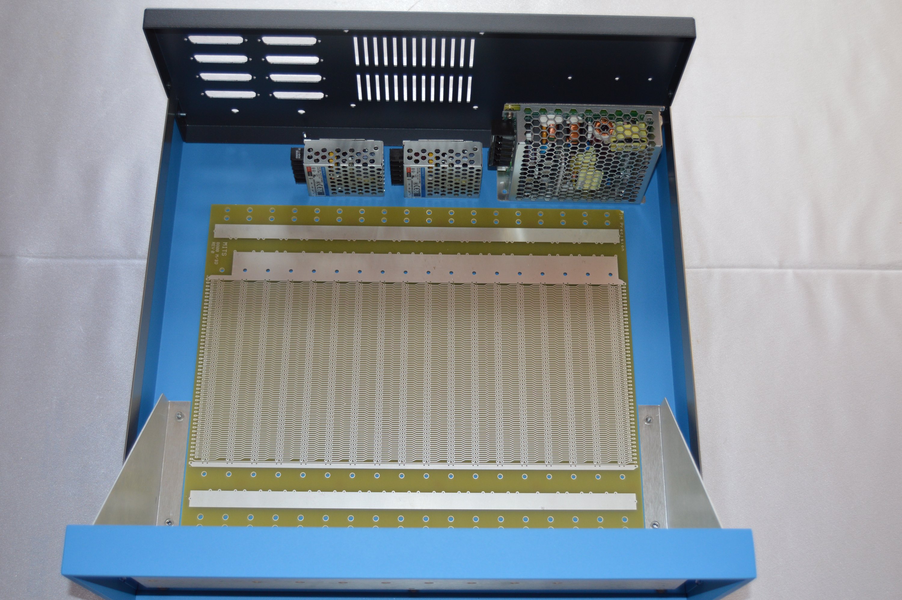
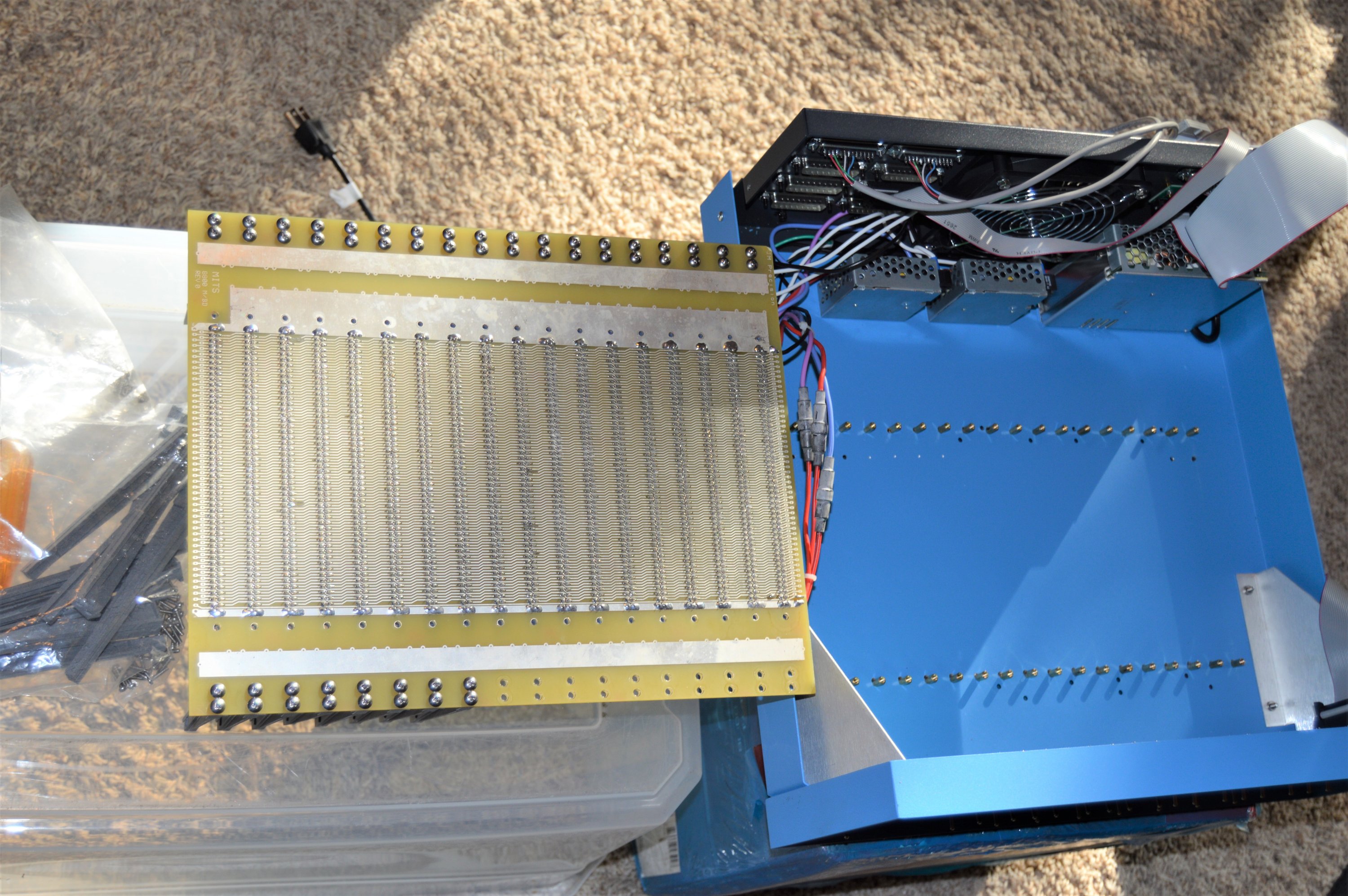
My second system uses an 18-slot backpanel from Jerry Walker at JMprecision.co.uk. It is an exact replica of the motherboard in the original Altair.
Both the 9-slot and the 18-slot backpanels fit in the chassis, but obviously the 18-slot takes up more space. It pretty much covers the whole inside.

Altair cabinet with 9-slot backplane |
Altair cabinet with 18-slot backplane |
You’ll notice I arranged the power supplies the same in both systems. They’re two 16v switching supplies and one 8v supply. Their signal grounds are not connected to chassis ground, so the 16v supplies can be made to provide +/-16v.
I decided to populate the 9-slot backpanel with all the indicator lights, jumpers and switches and the active termination circuitry. To tell the truth, the Altair won’t need any of that, but I assembled it that way, nonetheless. I socketed the terminator resistor packs with SIP sockets, so they can easily be removed.
I also have a terminator card for the 18-slotter but since I intend to run the original 8080 board, I won’t need termination. It’s just for later expansion, if I ever want to do it.
I’ve installed the edge connectors on the 18-slot motherboard, and that’s really all there is to that board. It’s weird how MITS applied power to it though. They just solder wires straight onto the board, without any connectors. So I did the same thing, but included three inline fuse holders.
Ready for the first power-on "smoke test!"
Both systems were setup and ready to go, but with all parts sitting on the table rather than mounted in the chassis.
I used a barrier strip to distribute power. Four conductors are for the AC input side and another four are for DC outputs from the power supplies.
The DC lines are black (gnd), red (+8v), violet (+16v) and blue (-16v). The AC side has neutral, line, fused and switched.
AC lines have neutral (black) and line (white) connected to the first two AC barrier-strip positions. Black is distributed to the neutral input on all power supplies. White goes out to a panel-mount 3A fuse and comes back to the third (fused) AC barrier-strip position. That goes to the power switch connector on the front-panel, and returns to the fourth (switched) AC barrier-strip position. The fourth position is what runs to the line input on all power supplies. I also run the fan off that. Earth ground is green and isn't connected to a barrier strip. It runs to chassis ground and to all the earth-ground connections on each supply.
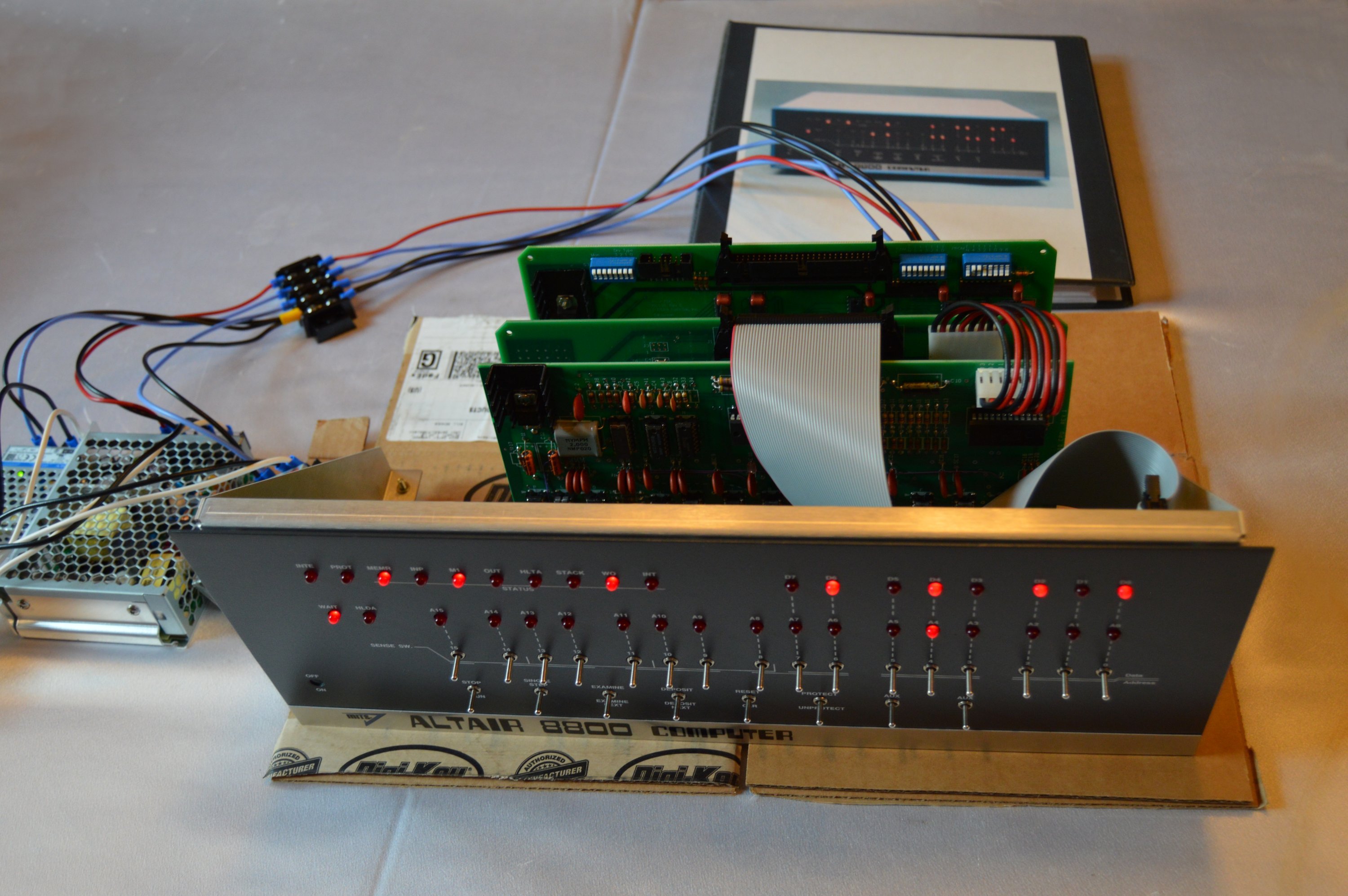
Bare-bones Altair 8800c |
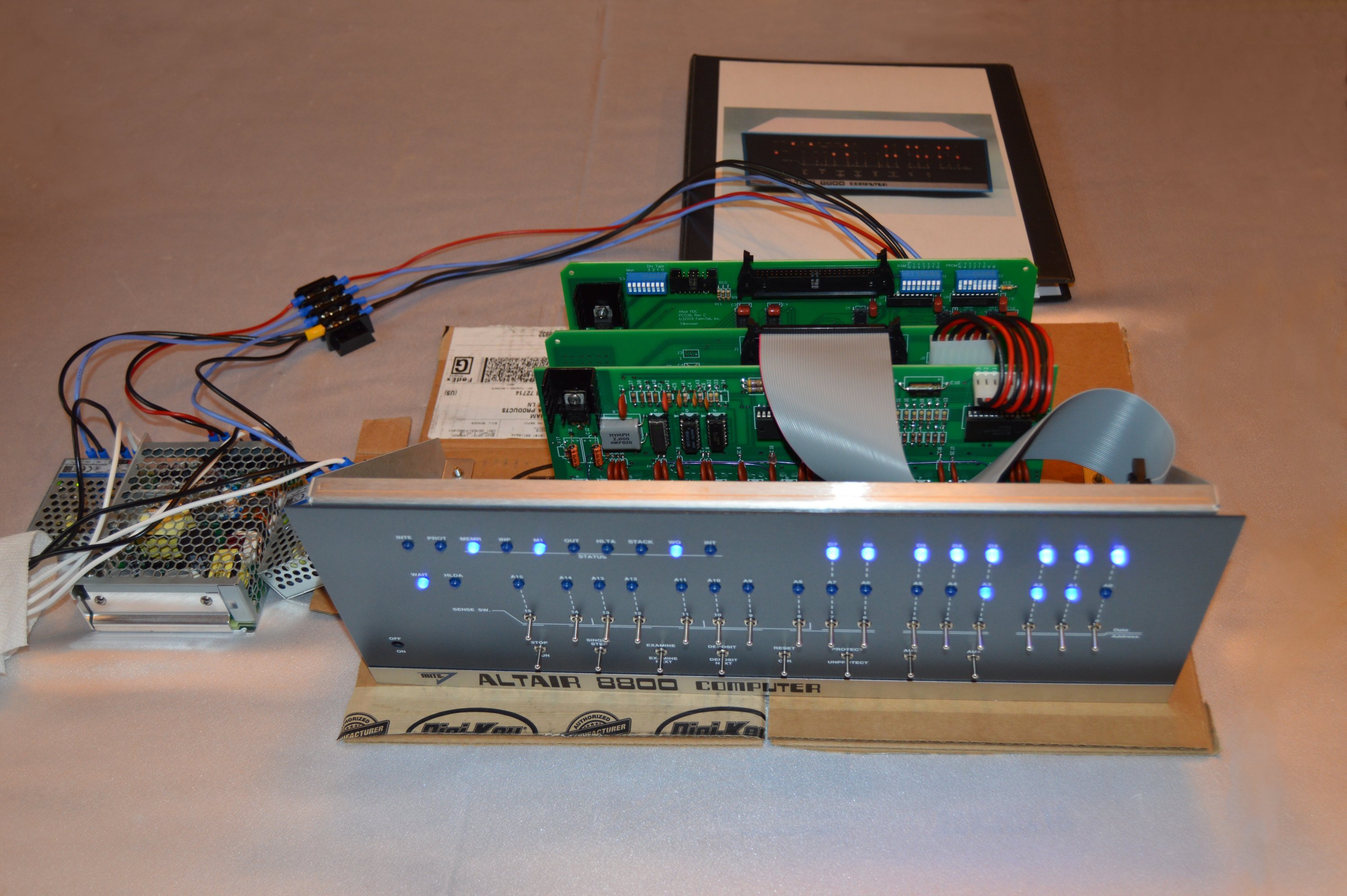
Altair 8800c front-panel with blue LEDs |
What? You say, "Altairs didn't have blue lights." What's that?!! I installed blue LEDs on the front-panel for the second system.
It definitely doesn't look original that way but I think it looks awesome. I'm pretty sure if blue LEDs were around when Ed Roberts made the first Altairs, he would have used 'em. I just thought my Altair 8800c - being a "restomod" of sorts - really needed blue front-panel lights.
So the one I made with the 18-slot backplane has red (original-lookin') LEDs on the front panel and the one with the 9-slot backplane is sportin' blue.
Let me fold that front-panel interface ribbon cable out of the way to show you the processor:
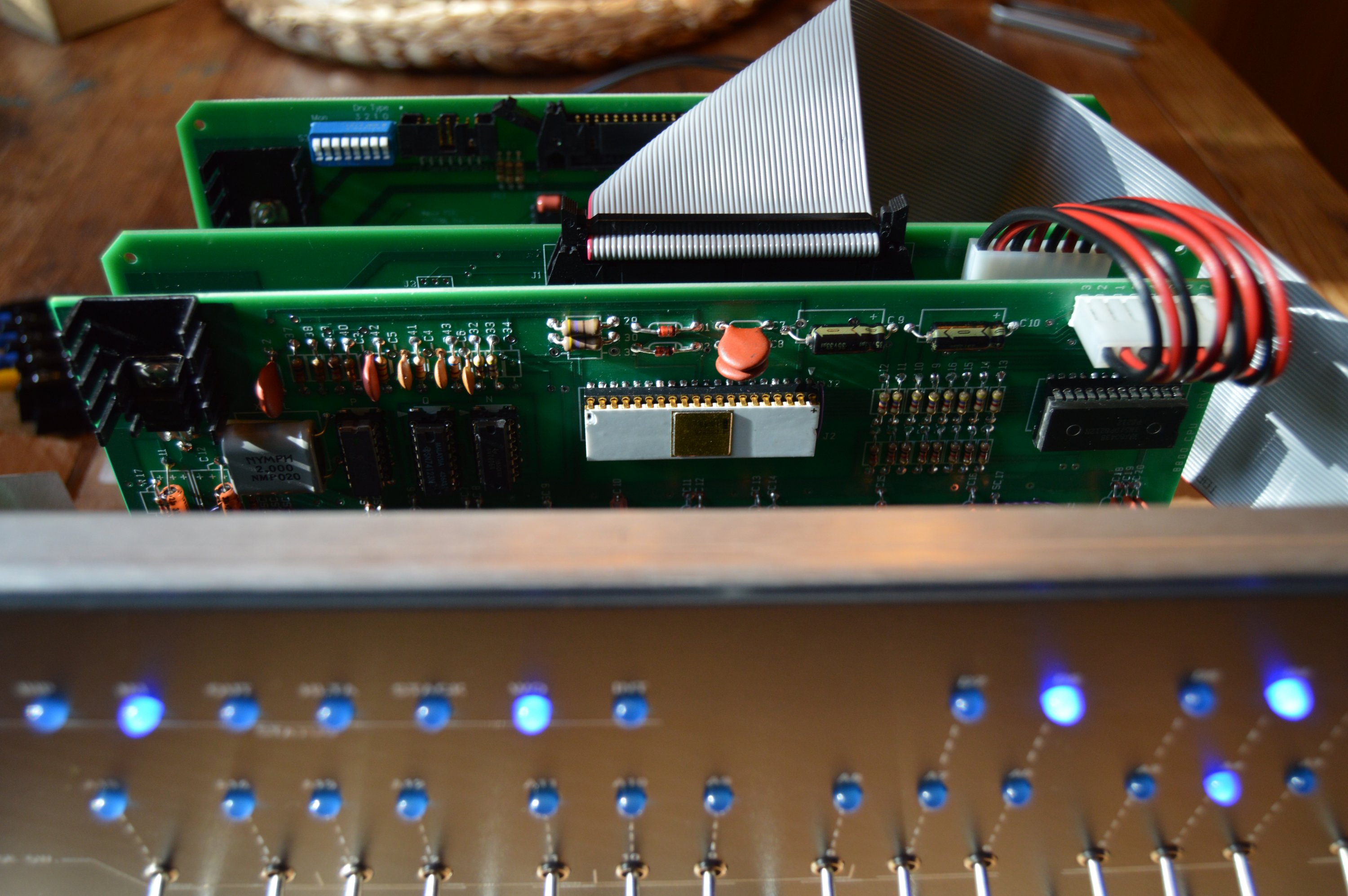
"Intel Inside" |
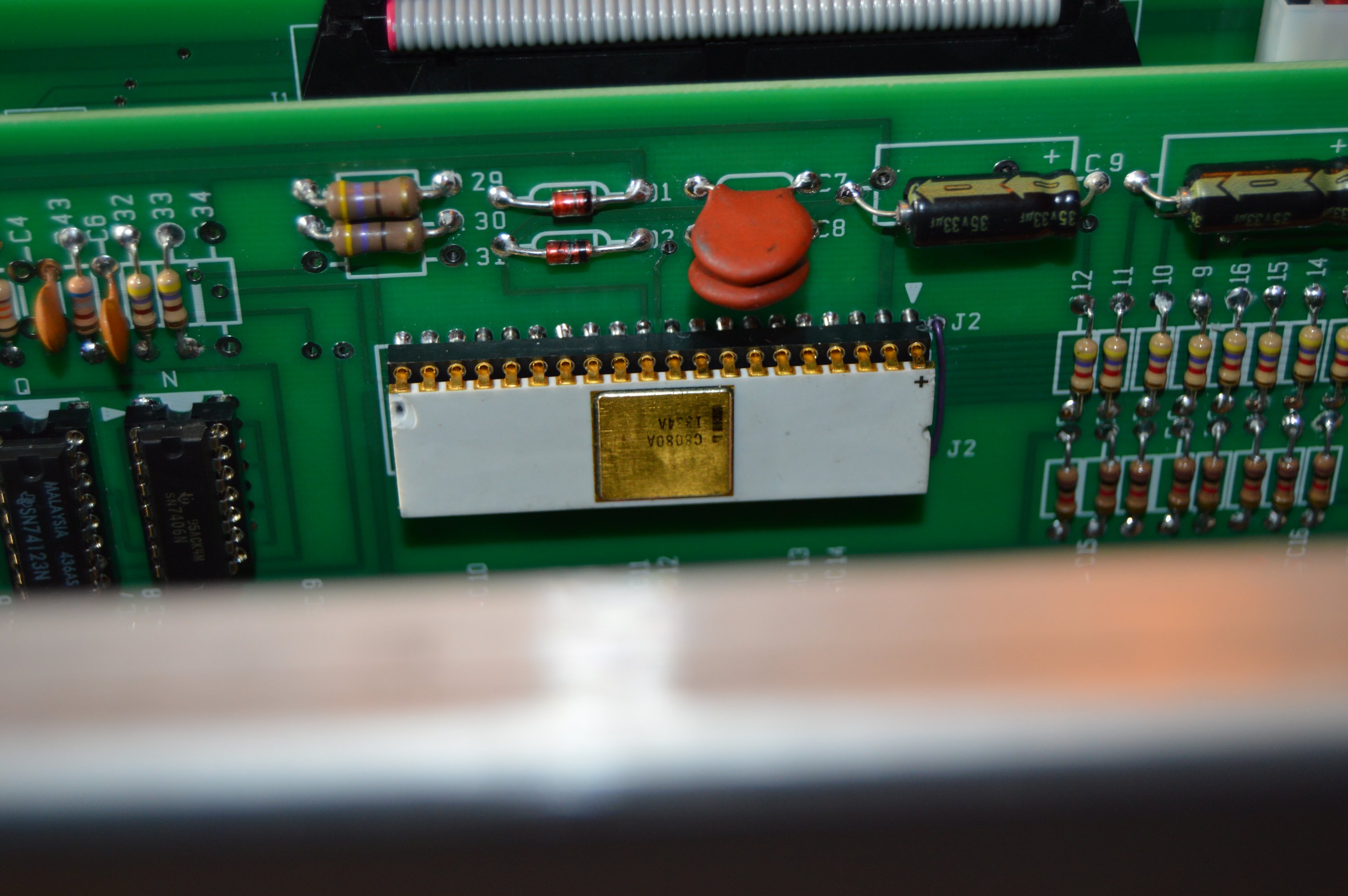
Ceramic 8080A, made by Intel in the 1970s |
Modern production 8080 processor chips work just fine – amazingly, they’re still made - but I had to swap-in the ceramic chip I had in my collection, just for fun. It still works.
Notice the damage to the ceramic near pin 20. I heard a rumor at one time, probably read it actually, that those were fairly common production defects and that Intel used to give 'em away as samples or perhaps sell them at discount. I also heard - actually read an interview with Ed Roberts - that this rumor started some drama back in the day because his competitors said Intel rejects were going into Altairs to keep the cost down. But that's was a rumor. See his response to that in the interview below.
Ed Roberts Interview in October 1984 Modern Electronics magazine
Next step was to wire the diskette interface connection. I soldered up the little 50-pin to 34-pin daughterboard adapter for the diskette drive. I configured the FDC+ board for drive type 5 and connected everything up to a Teac drive. I also configured the system to use Martin Eberhard’s AMON monitor at F800.
Applied power, set front-panel switches to 1 111 100 000 000 000, toggled STOP, RESET and EXAMINE. Then START - which executed AMON – and could use the HEX file uploader. My task was to upload Mike Douglas’ PC2FLOP program, which is used to create a boot disk (or any other, for that matter) from a disk image.
Bada-bing, bada-boom. Uploaded first try. Started execution at 0100h and voilà, "Houston, we have lift-off."
Told it to write to drive 0 and to transfer using port 0. Used Xmodem to send CPM22-48K-HDF.dsk and it started loading, and gave the progress indicator. My serial port is set to 9600/8/1/N so it wasn't incredibly speedy. But it was going!
I could see the diskette light go on, and eventually it kicked on the motor. It caches data before actually writing it. So the data transfer is continuous, but the disk writes are intermittent, writing blocks as they come.
A few important notes:
1. The FDC+ drive controller can be set in various modes to support a variety of disks.
2. When set as mode 4 or mode 5, the controller interfaces with TEAC FD-55GFR drives.
3. Mode 4 emulates an Altair 330Kb drive.
4. Mode 5 provisions for a 1.5Mb drive.
5. Either way, you must use HD media. Let me say that again. Even when the drive interface is configured for 330Kb, you must use HD media.
6. Disk images aren’t interchangeable, so use 330Kb images on Mode 4 and 1.5Mb images for Mode 5.
7. Mode 5 gives more disk space, but requires extra memory for its BIOS, leaving less for application programs.
So far, I’ve described mostly electronics. I've built the circuit boards, and I've hooked things up in a big pile on my desk. But we haven’t mentioned much physical layout and mounting. I've shown the backpanels and the power supplies sitting in the cabinet to give you an idea how they fit together, but I haven’t described any details yet.
So let’s explore that.
The Altair can be built without a card cage, but then the boards tend to wiggle in their slots if the cabinet is moved. Card cages stabilize the boards and prevent them from vibrating. They also help when boards are installed and removed, especially if the boards are fitted with ejectors.
I found several card guides online, but many of them are dimensionally inaccurate. This is true both for the two-piece card cage used on the 9-slot backpanel and the individual guides used on the 18-slotter. So I decided to create STL files myself, and to 3D print my own. I suggest you do the same, if you want card guides for your Altair. See the link below:
Altair Card Guides
The 9-slot backpanel and its card cage mounts using the existing holes in the Altair 8800c cabinet, so no drilling was needed.
The card cage leaves plenty of room for the components on the backpanel, should you choose to use them. You might have to lean a capacitor over or use small LEDs, but everything will fit if you're mindful during construction.
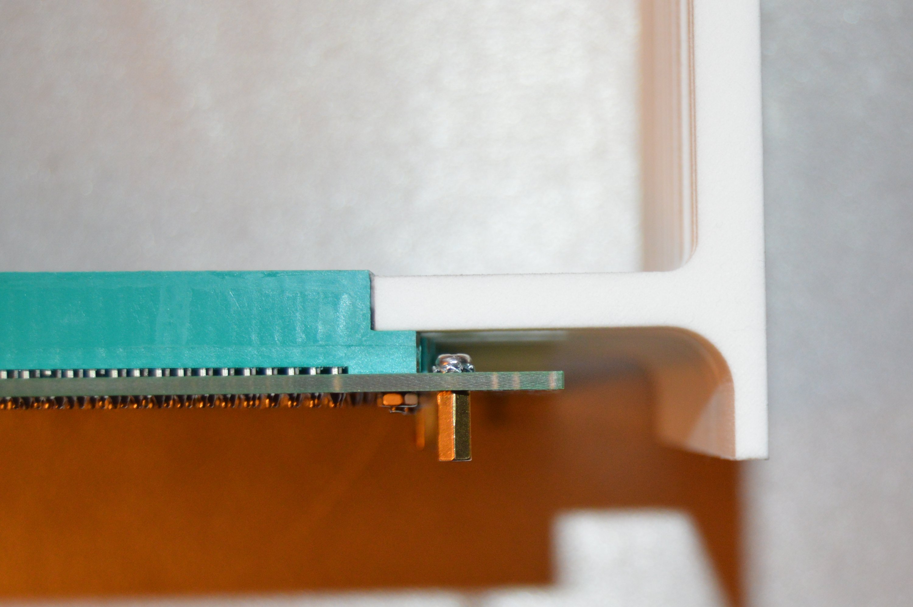
Room to mount components on the backpanel PCB |
M3x20 countersunk screws attach the card guides |
To install the 9-slot card cage and backpanel, you'll need the following hardware:
(18) M3x20 countersunk screws
(8) M3x10 threaded spacers
(12) M3 nuts
(4) star washers for M3 screws
(20) M3x6 screws (might want more for your power supply)
All 18 holes in the card cage / backpanel assembly use M3x20 countersunk screws. This keeps the screw head flush with the card cage so there's no interference with any circuit boards.
Underneath, use M3 nuts on slots 1, 2, 3, 5, 7 and 8. Use an M3x10 threaded spacer on slots 4, 6 and 9 and also use them on the outboard (IMSAI) holes nearest slot 1. Mount those outboard spacers with M3x6 screws and put a star-washer underneath the screw head. This will bite into the ground pad and provide good grounding.

Mounting hardware on the backplane solder side |
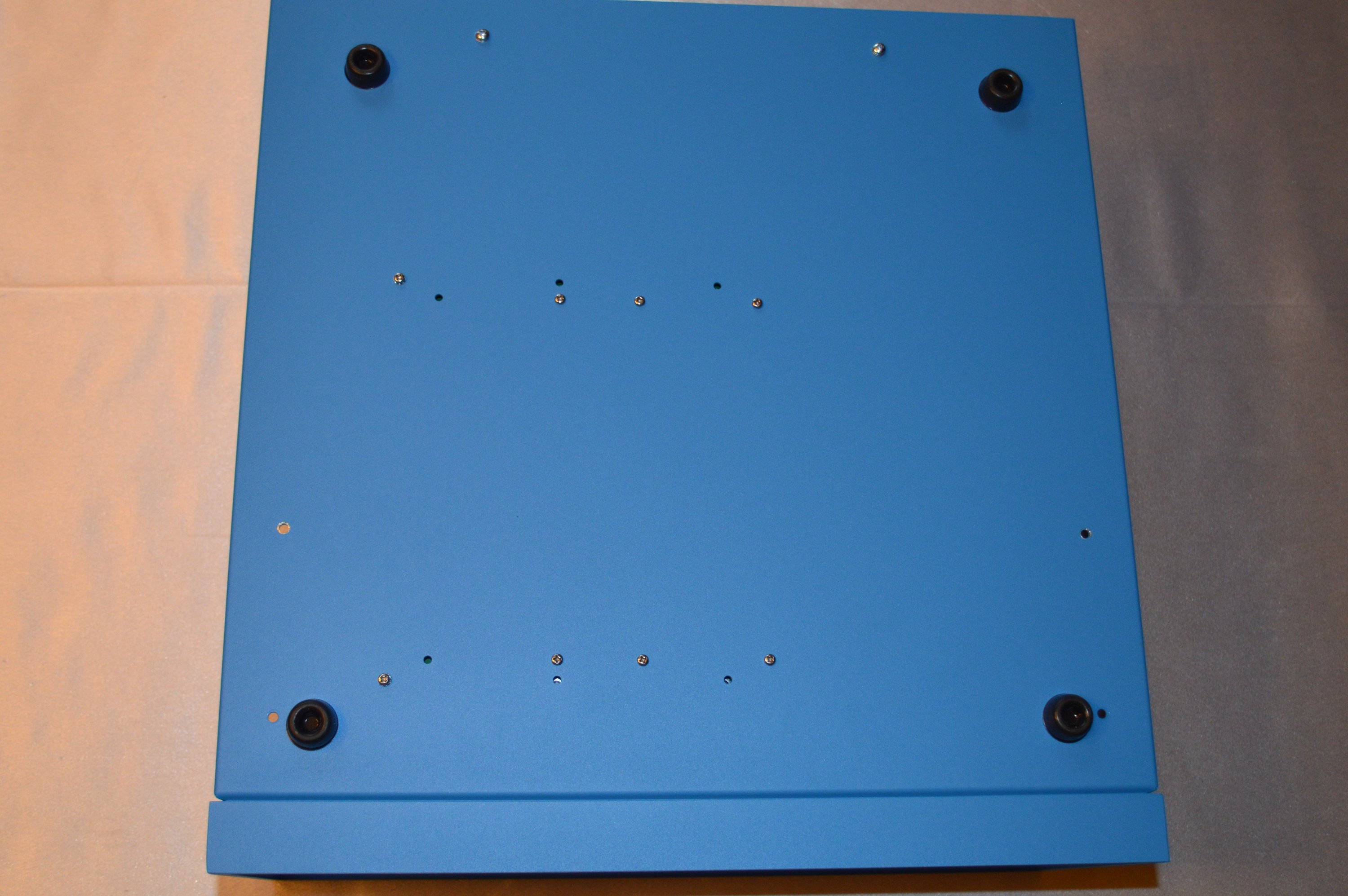
Bottom of cabinet, showing screws needed |
Underneath the cabinet, line up the holes with the threaded spacers and mount the board with M3x6 screws. The easiest way to do this is to get the assembly into position and thread one screw into place. Don't worry about the other holes - if the assembly rotates away, it's of no concern as long as you get one screw in. Then once you've done that, use the screw as a pivot to rotate the assembly into position to thread the remaining screws. Use a star washer under the outboard (IMSAI) screws to bite through the paint to ensure a good ground connection.
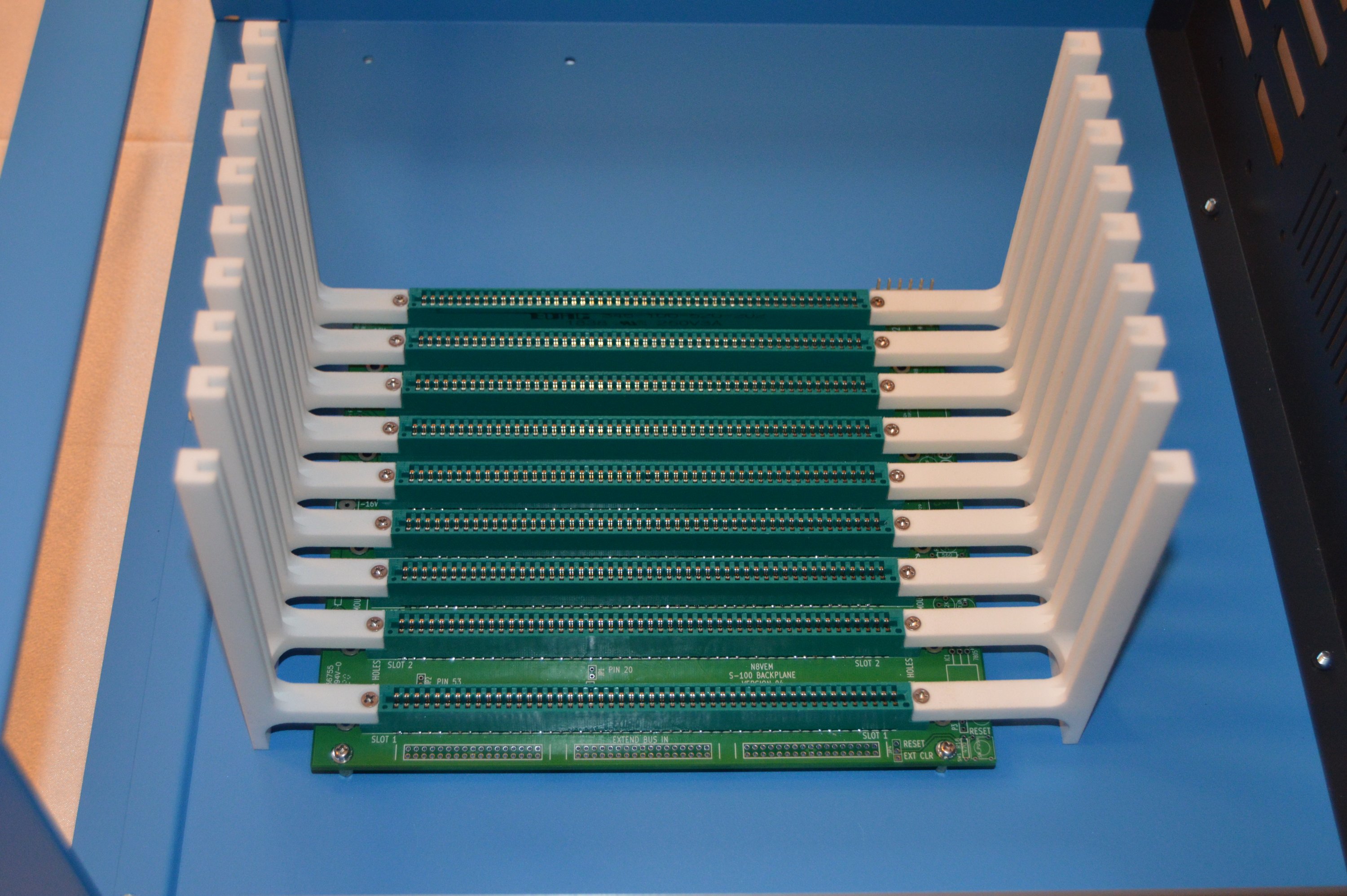
Backpanel and card cage assembly mounted in cabinet |

Board ejectors align with top of card cage |
The hardware needed for the 18-slotter follows:
(72) #6 x 3/8" Truss head Phillips wood screw - These are used to mount 36 card guides, a pair for each of the 18 slots.
(36) M3 x 10mm female threaded stand-off - These mount the board to the chassis.
(36) M3 x 12mm screw - These mount the board to the standoffs, going through the edge connectors.
(36) M3 x 6mm screw - These mount the standoffs to the bottom plate of the chassis.
Installing the card guides onto the 18-slot motherboard requires 72 screws. And the chassis must be drilled to mount the motherboard. You can use the motherboard to fabricate a drilling template out of cardboard.
Installing card guides on the 18-slot backpanel |
Backpanel mounted in chassis |
You can also see the stand-offs mounted in the chassis in the photo above. I put a standoff below each card slot, but I suppose a person could do every other one or maybe even fewer than that. But to me, the hardest part is drilling all the holes and getting them all aligned. I guess you could say I was "in for a penny, so I was in for a pound."
Next task is to wire everything up. Both systems - the one with a 9-slot backpanel and the other with an 18-slot backpanel - have power supplies the same position in both cabinets, and also distribute power the same way, using an 8-position barrier strip.
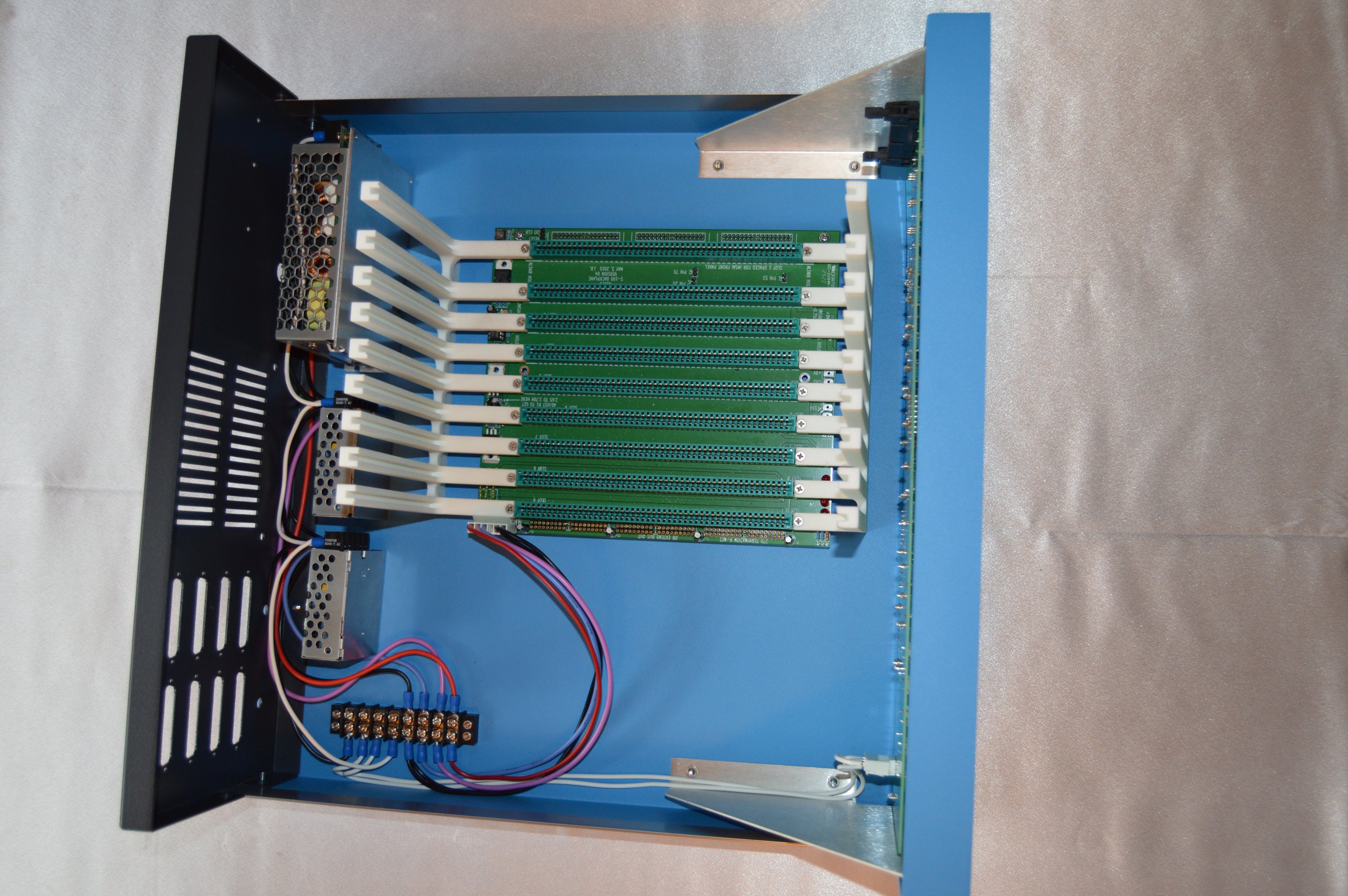
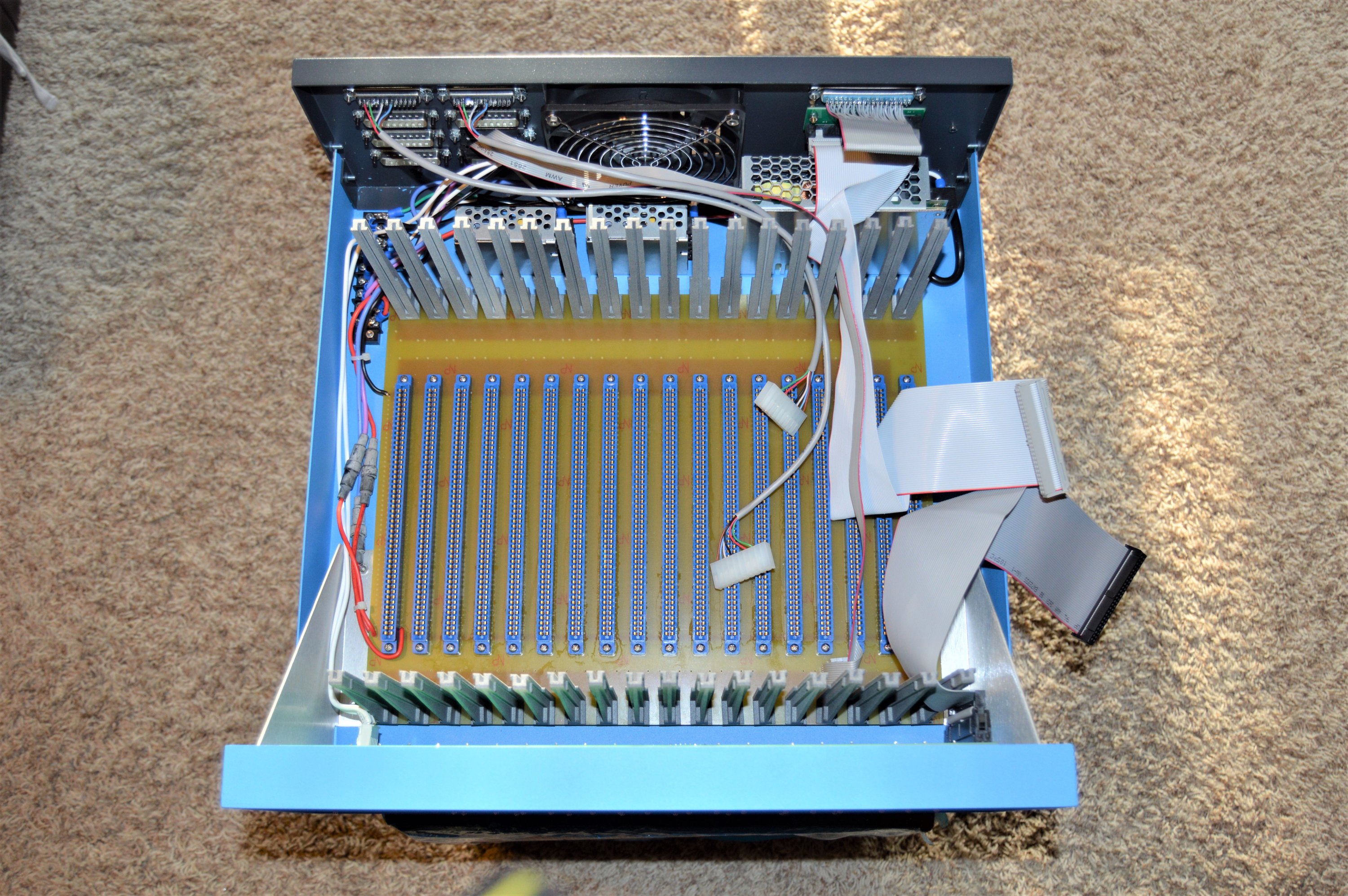
9-slot backpanel mounted in cabinet |
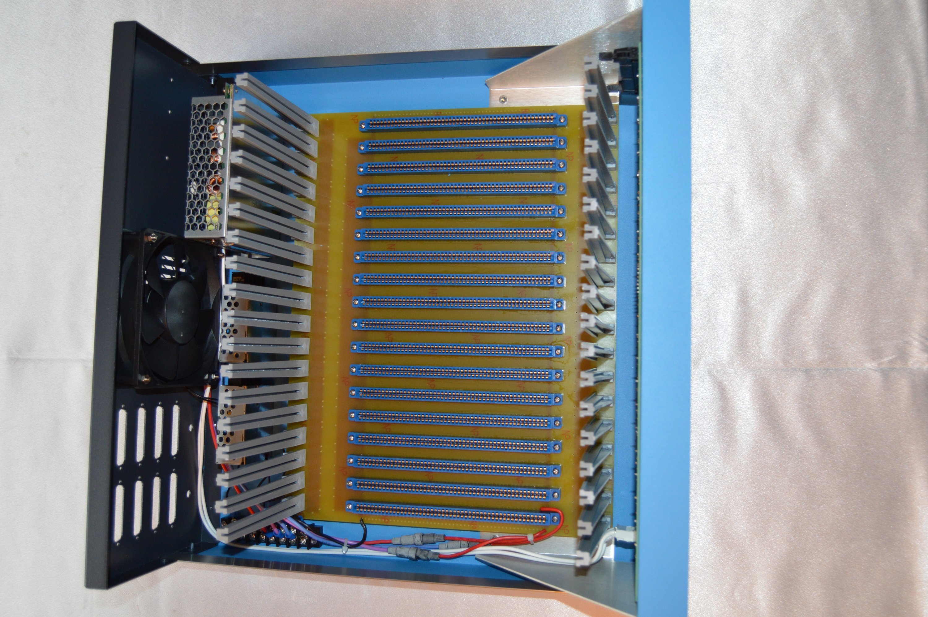
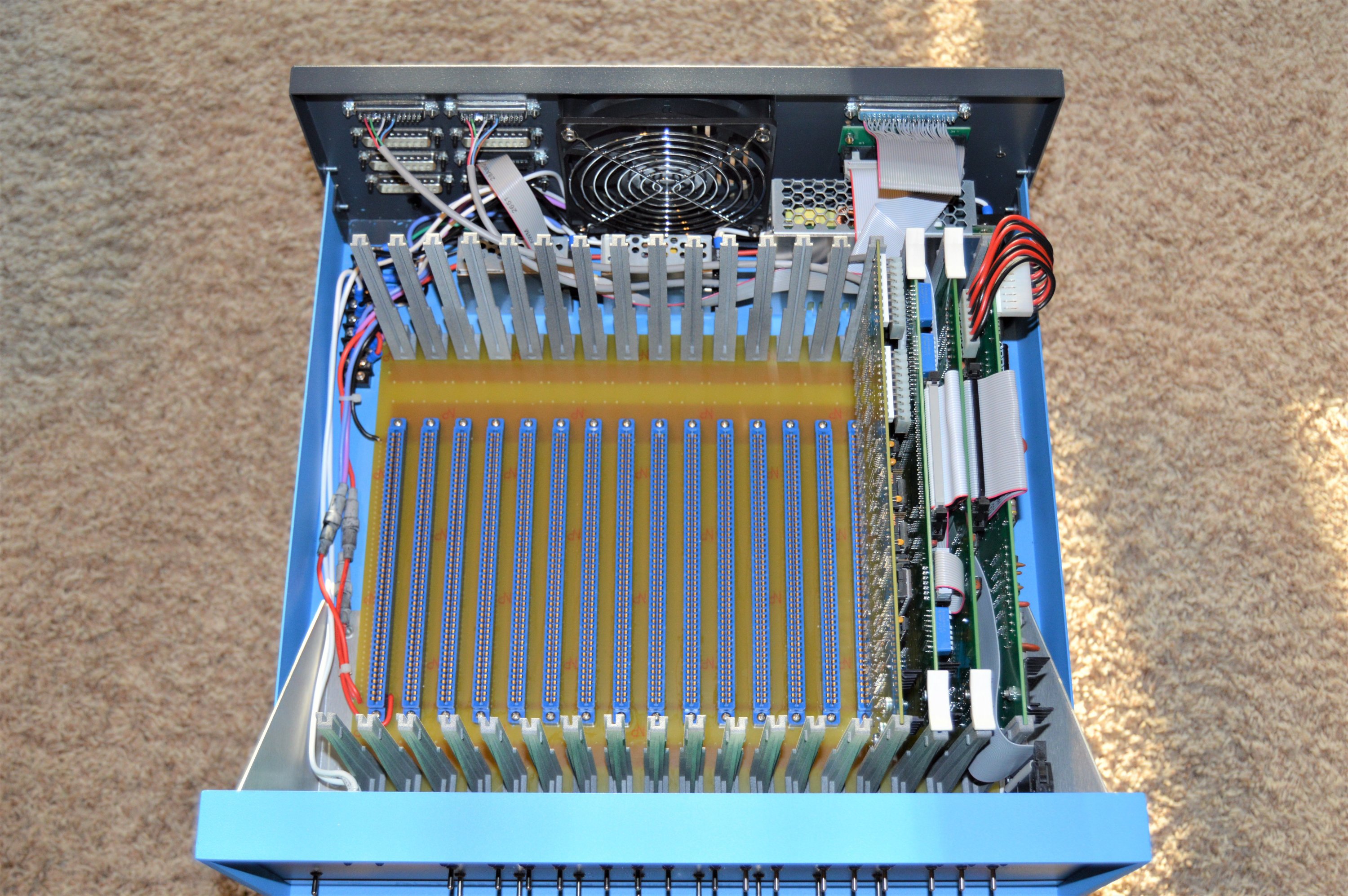
18-slot backpanel mounted in cabinet |
As you might guess, the 18-slot version is much heavier. Not only does it have more mounting hardware - (36) M3x10 threaded spacers, (36) M3x6 screws on bottom and (36) M3x12 screws on top - but it also has (36) card guides. And probably none of that adds as much weight as the board itself, which is 3.2mm thick. So it's a heavy board.
But not having a huge AC transformer keeps it much lighter than the original.
For power distribution, I had intended to use a pair of 4-position barrier strips, to keep the AC section away from the DC section. But I decided to go with a single 8-position strip.
AC is like this:
1. AC neutral
2. AC line
3. fused line
4. switched line
The DC side is simple:
5. Black Ground
6. Blue -16v
7. Violet +16v
8. Red +8
So the AC power line comes into 1 & 2. The (3A) fuse is connected between 2 & 3. And the power switch is connected between 3 & 4. So the AC line run to the power supplies comes from the #4 lug. AC neutral is connected to #1 and switched AC line is #4.
The DC section is just straight through - The output from each supply is connected to its respective lug on one side of the barrier strip, and then the other side is connected to wires going to the backpanel. For the 9-slotter, it goes to the PS connector. For the 18-slot backpanel, it goes through some inline fuses and then onto hard-wired soldered connections on the board.
For both the 9-slot and the 18-slot boards, I used a 10 amp fuse on the 8v line, and 1 amp fuses on the +/-16 volt lines. The 9-slot board is done with (socketed) picofuses and the 18-slotter is done with inline fuses. The power supplies are overload-protected, but fuses are an additional layer of protection.

Power supplies installed |
Inline DC fuses for the 18-slotter |
I could have just passed the disk interface ribbon cable through a DB-25 hole or out just under the cover. But that didn't appeal to me. I originally intended to modify the cabinet with a nibbler tool, but the cabinet is too nice to hack up that way. I'm sure I wouldn't have been able to cut a nice clean hole. So I decided to have a DB-37 disk drive connector hole cut at a machine shop in Tulsa called Ideal Specialty. They've done a lot of work like this for me over the years.
I considered buying a punch - looked on eBay for one - but they're too pricey. Even the more common DB-25 connector is pretty rare these days, and a DB-37, much more so. Punches are five hundred to a grand. Not worth it for a one-off. Ideal Specialty cut the hole precisely for under a hundred bucks.
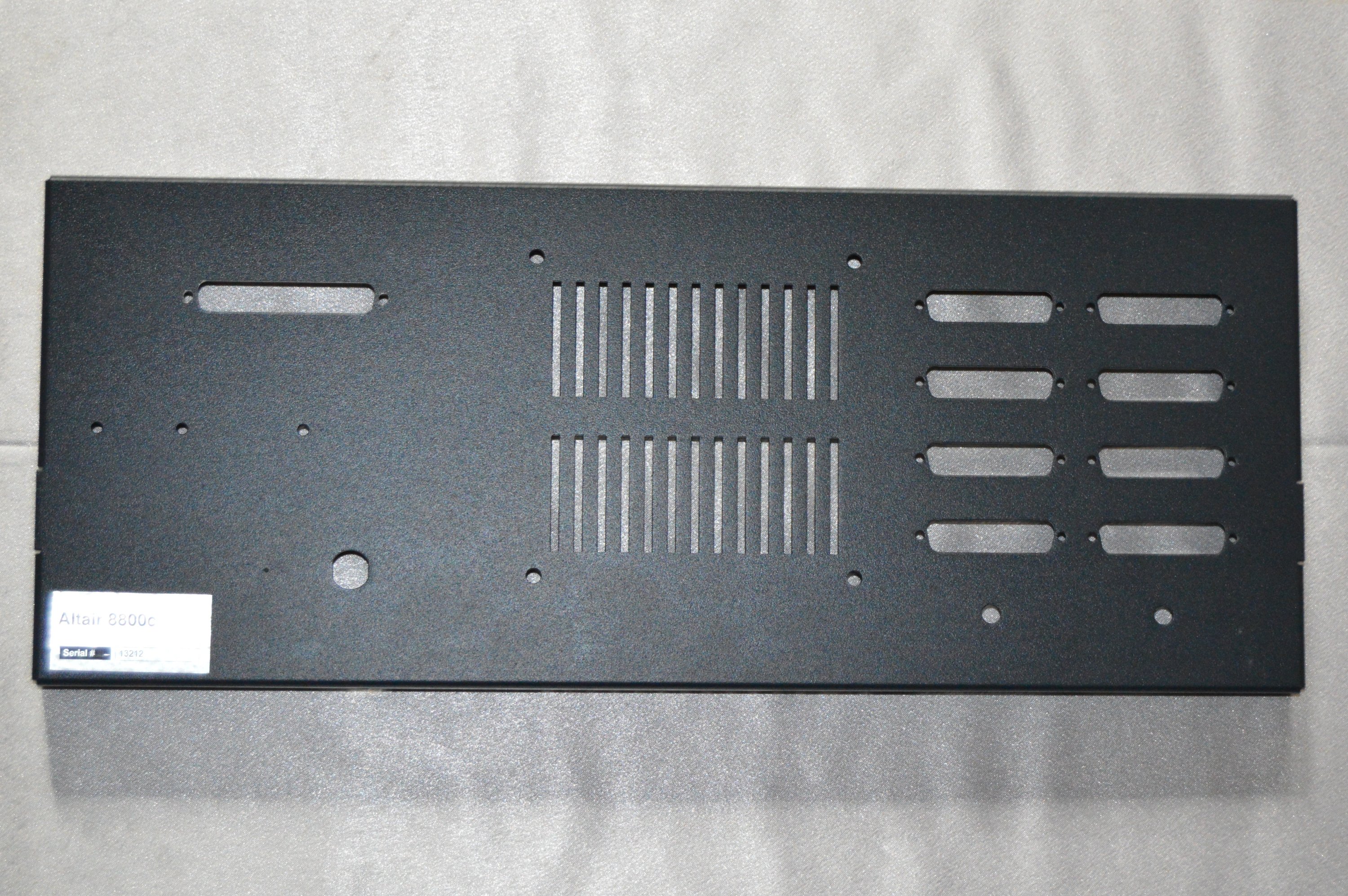
Rear panel with DB-37 diskette connector cutout |
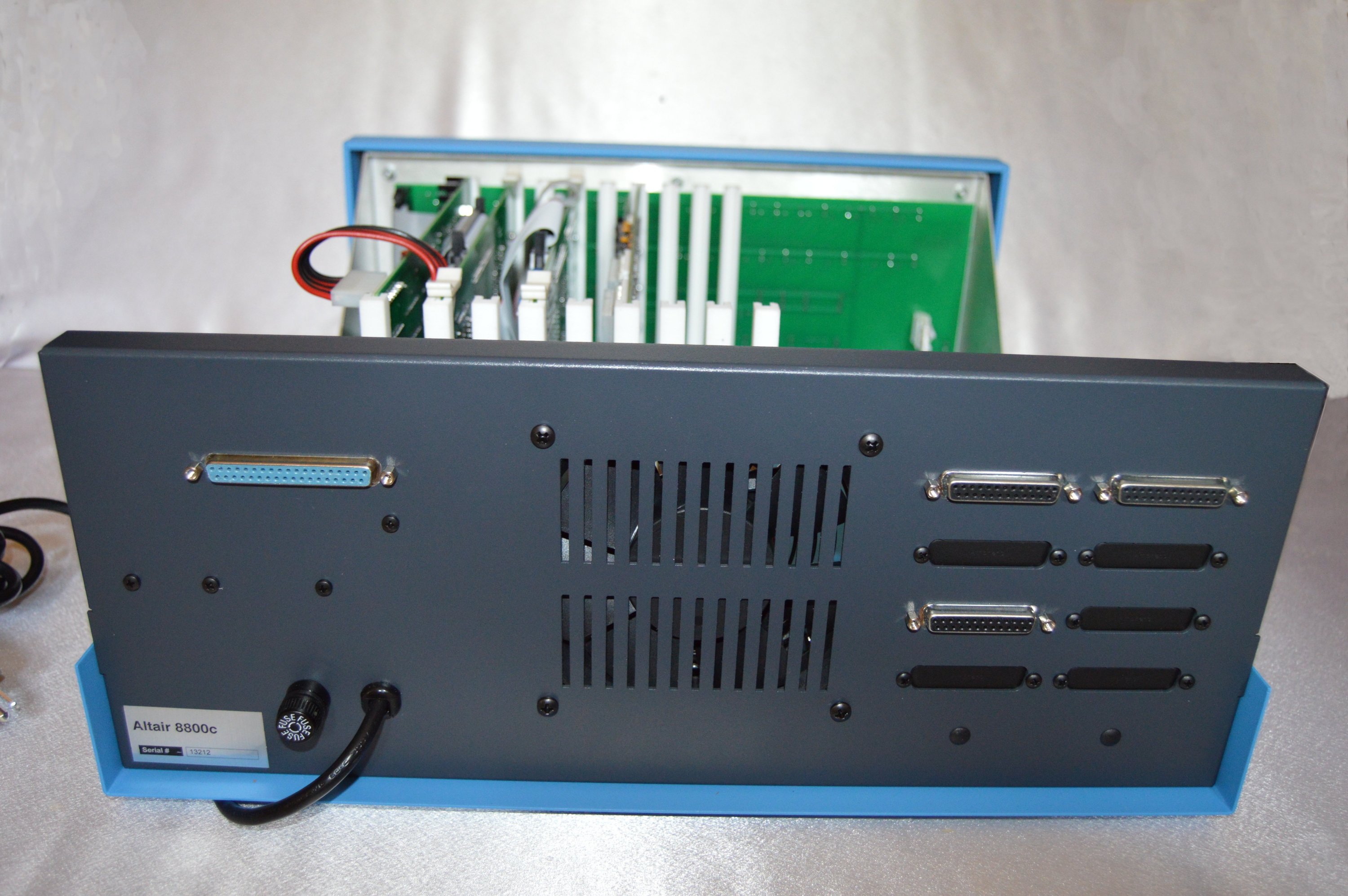
Rear panel with all components installed |
As you can see above, I only had the shop cut the DB-37 hole in the panel. I later drilled a 1/2" hole right beside the power cord for the fuse holder, and a 1/8" hole to mount the FDC+ diskette interface daughter board.
Ideal Specialty would have been happy to cut those holes for me too - and they could have cut the D-shaped hole for the fuse holder - but that didn't matter to me as much as getting the DB-37 cutout right. I knew I could drill round holes well enough. In fact, if you look closely at the photo of the panel above, you can see that I had already used a punch to mark the place where I was getting ready to drill the 1/2" hole for the fuse holder.
I initially bought stainless screws but later decided to get black ones. I also got some caps for the unused DB-25 holes and for the cassette jacks.
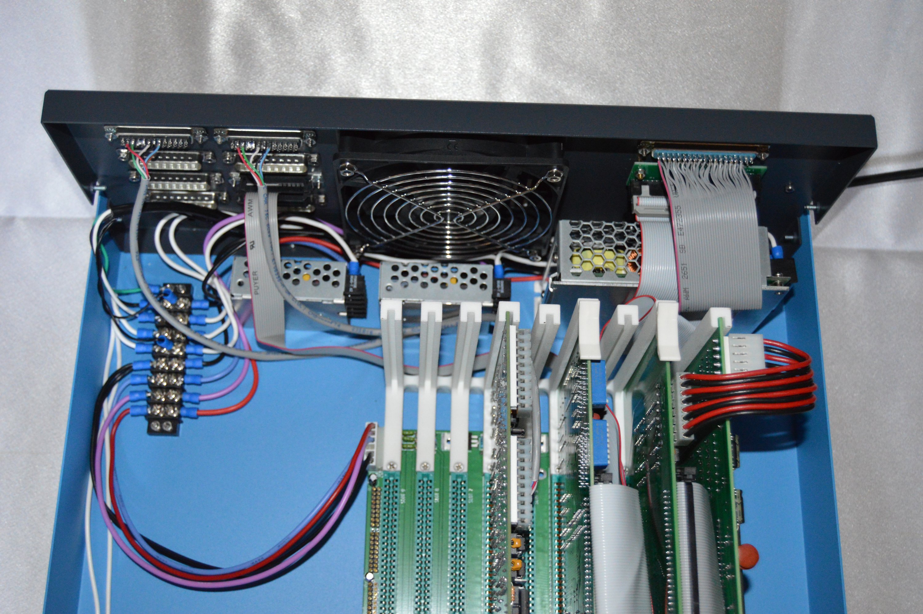
Internal wiring of the 9-slot system |
Internal wiring of the 18-slotter |
Internal wiring is nice and clean. The ribbon cables fold nicely to run between the slots and through the card cage, out to the connectors. The FDC ribbon cable connects to the 50-pin-to-34-pin daughterboard, which is mounted just below the DB-37. The DB-37 is connected to the 34-pin IDC too, straight through. It could have been done with a ribbon-crimp style connection - which I did on the 34-pin side - but I soldered the 37-pin connector.
The top two DB-25 connectors are the 88-2SIOJP ports and the DB-25 that's on the third row down is the FDC+ serial connection. All the rest of the DB-25 holes are plugged.
The processors are done! So let's talk about disk drives.
The FDC+ disk controller board can run in one of several modes. This allows it to support a variety of disk drives. I chose to use TEAC FD-55GFR diskette drives because they are reliable, provide good stortage density and are still pretty plentiful. Media for them is still available too. The FDC+ board supports this drive in two modes: Mode 4, which emulates an Altair 8" 330Kb diskette drive and Mode 5, which is a Douglas proprietary format, supported by a custom version of CP/M that provides 1.5Mb per diskette.
I mounted my diskette drives in a "generic" KRI Computer CK7021 dual 5-1/4" drive case. There are other good options, but this case worked nicely for me. It includes a power supply and has two bays, which is a useful configuration. And it has a rear panel with cutout that works nicely for DB-37 fitment.
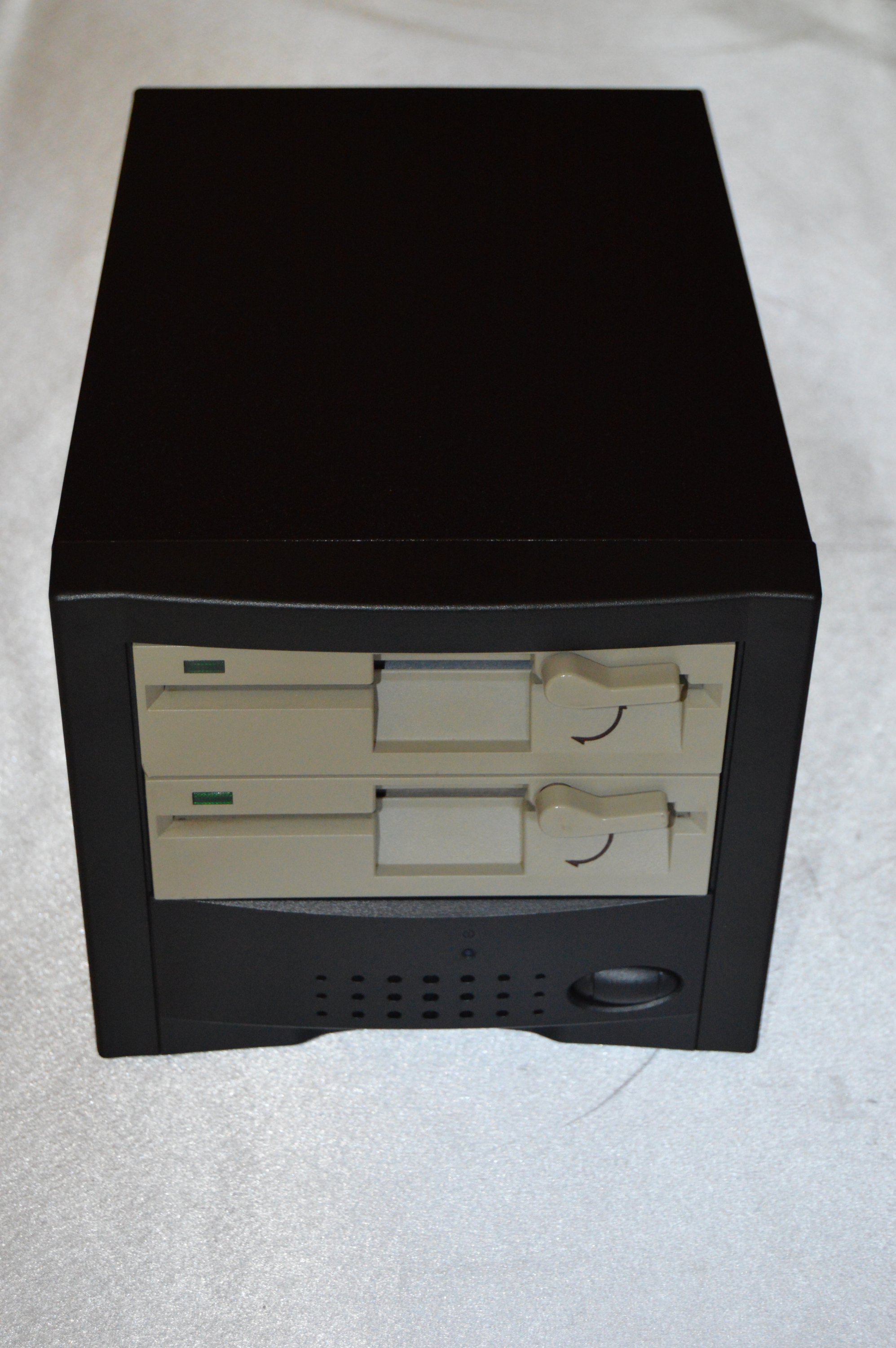
Diskette drive case |

Back of the diskette case, showing DB-37 interface connector |
Having DB-37 connectors makes interconnect between procesor and drives clean and convenient. The connector cable is a three-foot DB-37 straight-through cable. They are still readily available, as are five-foot variants.

CPU and diskette drive connected |
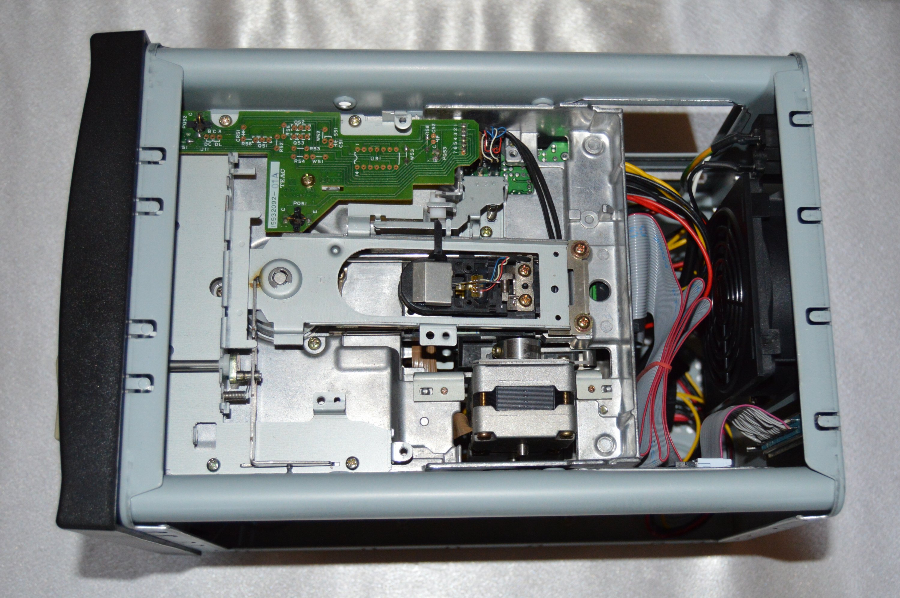
Internal wiring of diskette subsystem |
The ribbon cable inside the diskette cabinet is a straight connection - none of that PC-era twisted cable stuff - and it runs to a 34-pin IDC connector. That connects to a short 34-pin-to-DB37 cable.
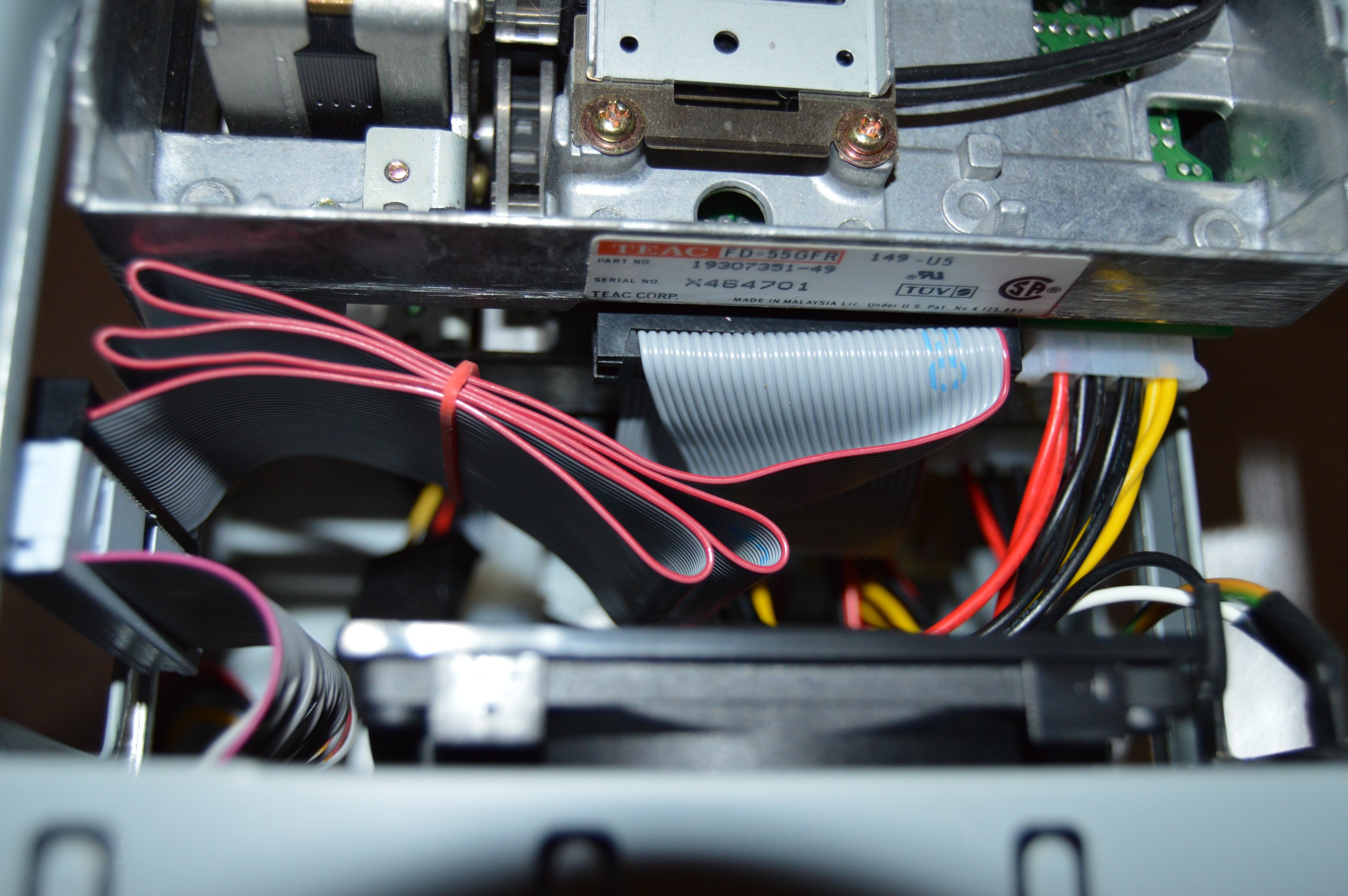
Close-up of the internal ribbon cable |
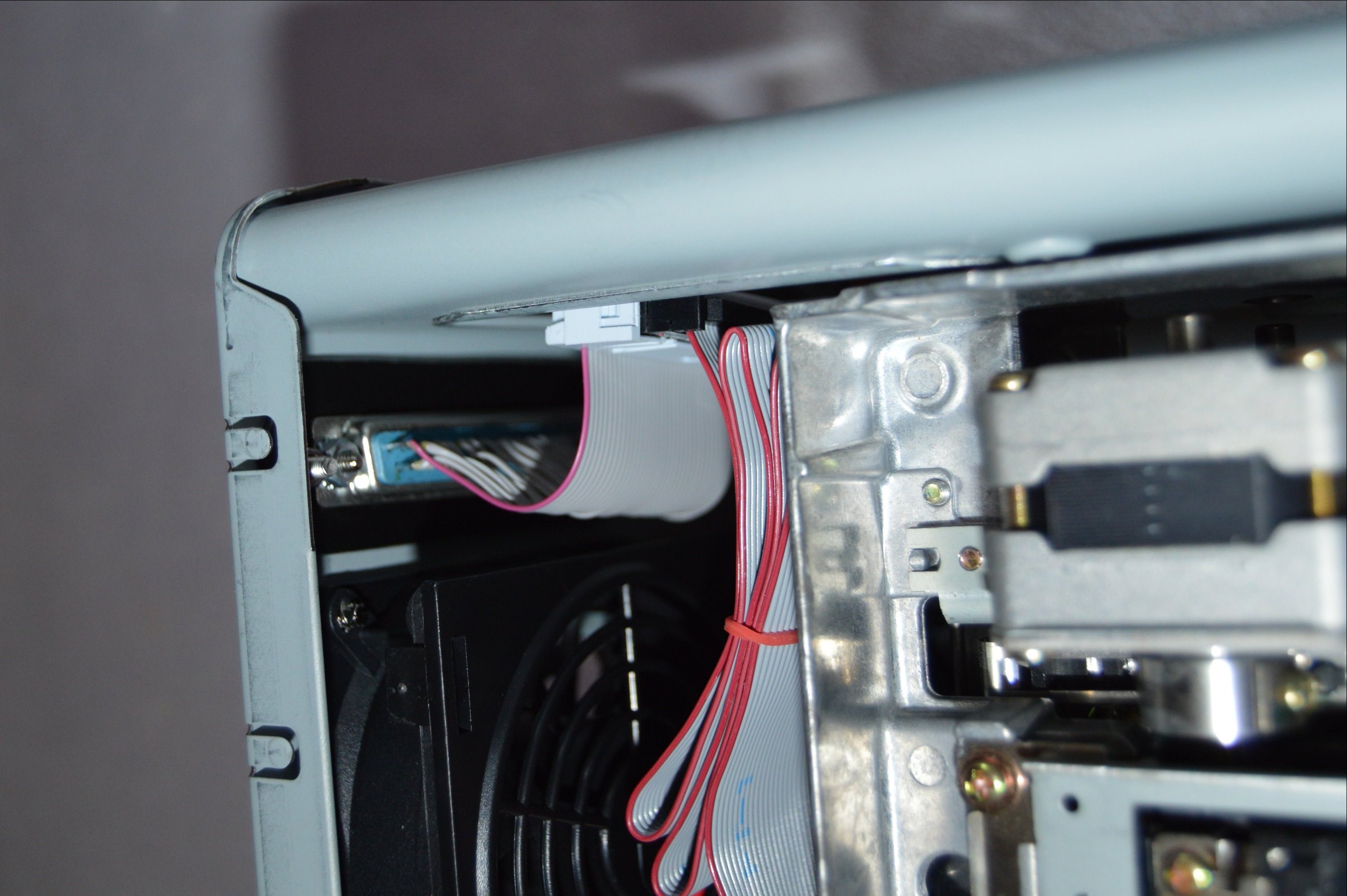
Close-up of the DB-37 connector |
While I'm on the subject, I took a few minutes to document the switch settings and jumpers for each of the boards. I was really only interested in a couple of configurations: (1) Boot from disk using the FDC+ loader, and (2) start from ROM using one of Eberhard's boards, e.g. Amon or BASIC. So below is a list of settings for each of those configurations.
There is nothing below that isn't already documented in the manuals, but I found it helpful to make notes to tell me exactly what switches to set for each of my favorite setups.
======================================================================

For the settings described below, the switches set to "up"
or "on" are defined as "1."

To use Mike Douglas' disk loader at FF00, use these settings:

FDC+
S1 Ram - all zeros
S2 Rom - all ones
S3 Drv - 00000, so 00000100 for 330Kb or 00000101 for 1.5Mb

88-2SIOJP rev G
SW1 - 00011111
SW6 - 00000000
SW2 - 11011101
SW3 - 10000110
SW4 - Port 1 baud
SW5 - Port 2 baud

- or -

88-2SIOJP rev H
SW1 - 000000000
SW2 - 000000000
SW3 - 11011110
SW4 - 100000000
SW5 - Port 1 baud
SW6 - Port 2 baud

This will boot at FF00 and expose all the rest as RAM.

Boot procedure:

1. Stop / Reset
2. Set front-panel switches to 1111 1111 0000 0000
3. Toggle Examine
4. Toggle Run

======================================================================

To use Martin Eberhard's Amon on ROM (rev G board):

FDC+
S1 Ram - all zeros
S2 Rom - 01111111
S3 Drv - 00000, so 00000100 for 330Kb or 00000101 for 1.5Mb

88-2SIOJP rev G
SW1 - 00011111
SW6 - 00000000
SW2 - 11011101
SW3 - 00000110
SW4 - Port 1 baud
SW5 - Port 2 baud

This will start Amon at F800 and expose all the rest as RAM.

Startup procedure:

1. Stop / Reset
2. Set front-panel switches to 1111 1000 0000 0000
3. Toggle Examine
4. Toggle Run

At the prompt, type "BO" to boot from disk. Or type "?" for a menu.

======================================================================

To use Martin Eberhard's BASIC on ROM (rev H board only):

FDC+
S1 Ram - all zeros
S2 Rom - 01111111
S3 Drv - 00000, so 00000100 for 330Kb or 00000101 for 1.5Mb

88-2SIOJP rev H
SW1 - 000000000
SW2 - 000000000
SW3 - 11011110
SW4 - 000000000
SW5 - Port 1 baud
SW6 - Port 2 baud

This will start BASIC at C000 and expose 48Kb RAM. Alternatively,
you can boot disk at FF00, also exposing 48K of RAM (and maintaining
BASIC in ROM).

Either way, you must start using the following method:

1. Stop / Reset
2. Set front panel address switches to the desired starting address (C000 or FF00)
3. Examine
4. Set all front-panel switches to zero (to boot from port 0)
5. Toggle run

======================================================================
Quick note: The configurations above do not take advantage of one of the coolest features of Eberhard's 2SIOJP boards - The automatic ROM disable, which allows access to a full 64K-bytes of RAM for software. So if you have a 2SIOJP board, you might want to configure your system to allow ROM auto-disable.
Here are my two 8800c systems, one with a 9-slot motherboard and the other with an 18-slot motherboard. I call the former "Blue" and the latter one, "Red." You can see why from the photo below:
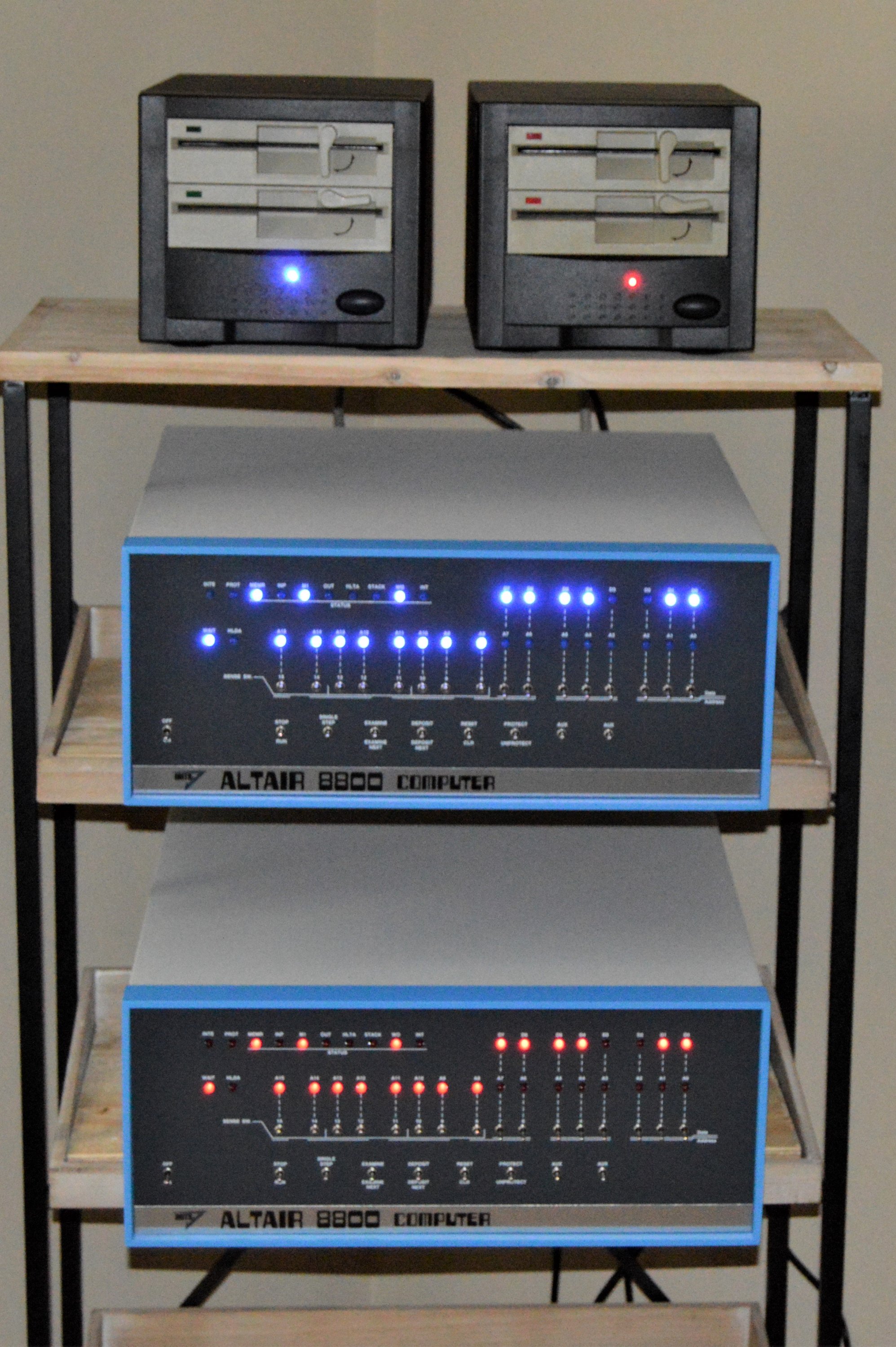
"Red" and "Blue" ready for action
Funny thing is I even replaced the disk access LEDs on the drive connected to "Blue" with blue LEDs. Not obsessive at all.
Click the photo above to see a litle video of "Blue" running some code, showin' the blinkenlights. I initially had the systems sitting on shelves, but I decided to get a 19-inch EIA rack like was used for minicomputers. They're still popular for servers and networking gear, so you can find 'em in various heights. The wires behind the Altairs were just too unweildy when they were sitting on the shelves, 'cause I have cables going to terminals and to RS-232-to-ethernet adapters and they're all connected to an ethernet switch. All that stuff mounts nicely in the bottom of the rack, while the Altairs and their disk drives sit on shelves.
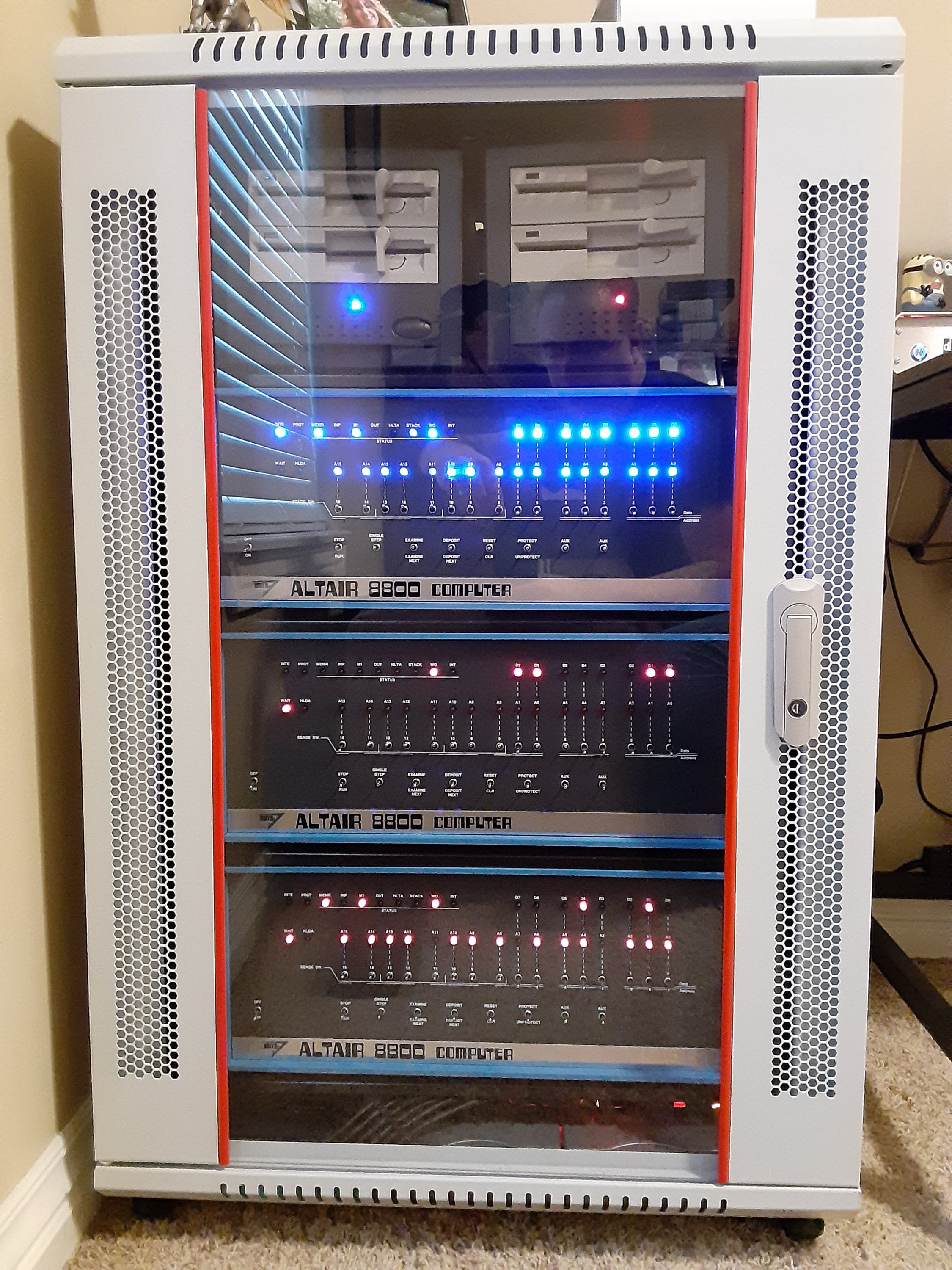
Altairs in a 19" EIA rack
In addition to "Blue" and "Red," there's a clone on the bottom shelf. Right now, "Blue" is configured to boot 1.5Mb diskettes and "Red" is configured for 330Kb. Might change 'em later. For sure I want to try the FDC+ serial drive server setup. That's gotta be cool!
But wait, there's more!
Want an 8Mb IDE disk (magnetic or compact flash) for your Altair? See the link below for the low-down on that.
A few words about software, before I go. You might want to download disk image files from the links below.
330Kb CP/M diskette images
1.5Mb CP/M diskette images
PC2FLOP 330Kb disk loader tool
PC2FLOP 1.5Mb disk loader tool
If you own an Altair, you simply must own a copy of Zork. While you're at it, journey through the lands of Jinx, which is my own creation and follows in the tradition of Zork.
No Altair system is complete without WordStar. It's a pretty competent word processor, and was definitely a big deal back in the 1980s. Still very easy to use, especially when compared with other text editors of its time.
And of course, you must run Microsoft BASIC and all the popular programs that circulated back in the day. A bunch of popular programs were published by David Ahl in his popular magazine, Creative Computing. Plus there is Eliza and StarTrek, which were hugely popular at computer club meetings in the 1970s.
Lastly, if you want a C compiler for the Altair, check out both BDS C and Aztec C. I personally prefer Aztec C but BDS is useable and definitely holds its place in microcomputer history.
Each of those is available in the downloads linked above.
Just gotta say,
"Real computers have front-panels!"
Resources:
Altair 8800 Archive - Collection of documentation, disk images, executable binaries and source code for the Altair 8800 and clones
BASIC programs for the Altair and other systems with Microsoft BASIC
C Applications Source - Source code for C applications
The Altair 8800: The Machine that Launched the PC Revolution, Article by PC Magazine
Altair 8800 Microcomputer, Collection item description by the Smithsonian Museum
MITS Altair 8800 Computer, Article by OldComputers.net
Altair Clone Kit by Mike Douglas at AltairClone.com
AltairDuino Kit by Chris Davis at Adwater & Stir
Arduino Altair 8800 Simulator Kit by David Hansel at Hackster.io
Altair 8800 Reproduction Boards and Parts from Mike Douglas at DeRamp.com
Altair 8800 Reproduction Boards and Parts from Gary Kaufman at The-Planet.org
Altair 8800 Reproduction Boards and Parts from Jerry Walker at JMprecision.co.uk
S100 Computer Parts and Circuit Board Boards from Todd Goodman at S100computers.com
Altair 8800 Re-Creation Kit by Grant Stockly at AltairKit.com
Parham Data Products